عضویت
عضویت  ورود اعضا
 راهنمای خرید


Flat heating plates0 pages
for housings, switch cabinets and devices
>
>
>
>
>
Low surface temperature
Limited space requirement, just 3mm thick
Even heat distribution over the whole surface
Without ventilator – no dust whirls
Maintenance-free, long service life
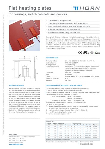
Housings with electrical, electronic or mechanical installations are often subject to temperature fluctuations, which lead to condensation, corrosion and leakage currents. In order
to guarantee the functional safety of these installation elements, it makes sense and
is cost-efficient to create a balanced inside temperature. HORN heating consists of an
anodised 1.5 mm thick aluminium plate vulcanised onto a 1.5 mm thick silicone heating
film. A small amount of space is required thanks to this flat construction and extensive
heat radiation is still provided.
B
B1
H
H1
TECHNICAL DATA
Operating voltage
Electrical power
Heating element
Surface temperature
B2
220 – 240 V, 50/60 Hz alternative 115 V, 50 Hz
40 W, 100 W, 200 W
Silicone heating
With bi-metal 65/45°C controller, higher temperatures
can be reached without a temperature controller
depending on the environmental conditions
0,5 m line 2 x 0,75 mm2
Aluminium
Retainer bracket on TS 35 mounting rail or M4 screws
IP X4 / 1
VDE + UL
H2
o4
,5
L2
L
L1
Technical changes are reserved. All details are provided without liability. The specified information does not release the customer from the obligation to perform independent application tests. / 15.10.2012
Flat heating plates
Connection
Plate
Fixing
Protection type/class
Approvals
INSTALATION NOTES
ESTABLISHMENT OF NECESSARY HEATING POWER
Installation must take place according to the valid
VDE and CE guidelines for the respective application.
The corresponding protection measure and contact protection are to be realised by the user with
installation. To achieve good temperature control
in the full space in the housing, the heating plate
should be mounted in the lowest area. A distance
of at least 10 mm to the side walls and 50 mm to
the underside is required so convection can form.
A distance of 35 mm to thermo-plastic parts is
recommended. A separate room temperature controller in front of the heating plate must be switched
to control the inside housing temperature.
The necessary heating power depends on the following parameters:
> Location (inside, outside), switch cabinet size (surface)
> Environmental temperature, material, insulation, loss power of installed components
> An estimated calculation is possible as follows:
a.) Standstill heating: inside P = T (K x A)
outside P = T (K x A) x2
b.) Operating heating: inside P = T (K x A) – Pv
(Installation devices switched on) outside P = T (K x A) x2 – Pv
P = required heating power
T = Temperature difference between the required average switch cabinet inside
temperature and environmental temperature
K = heat transmission figure (for steel sheet metal 5 – 6 W/m2 K)
A = overall free-standing housing surface in m2
Pv = overall installed loss power in W
ORDER DETAILS
El. power
Watt
Voltage
Volt
Temperature
controller
L
L1
L2
Dimensions in mm
B
B1
B2
20
230
none
150
134
40
80
64
60
1,5
ca. 3 ca. 7
106978
40
230
65°C
150
134
95
80
64
46
1,5
ca. 3 ca. 13
107046
107190
H
H1
H2
Type No.
70
Horn GmbH
Gewerbestraße 14 / 78244 Gottmadingen
Fon + 49 (77 31) 78 03 - 0
Fax + 49 (77 31) 78 03 - 92
info@horngmbh.com
www.horngmbh.com
230
none
200
180
40
150
130
60
1,5
ca. 3 ca. 7
100
230
65°C
200
180
95
150
130
46
1,5
ca. 3 ca. 13
107412
80
230
none
300 280
40
200
180
60
1,5
ca. 3 ca. 7
107424
200
230
65°C
300
95
200
180
46
1,5
ca. 3 ca. 13
107428
280
All designs are also available in a 115 Volt version.
Fixing brackets to clip the heating elements onto a profile rail (TS 35) > 150 mm length type 50168
> 200 mm length type 107547
> 300 mm length type 50169