عضویت
عضویت  ورود اعضا
 راهنمای خرید


Model: 4801 pH Controller0 pages
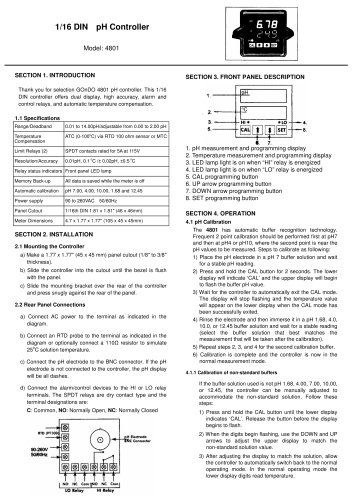
1/16 DIN pHController VlcdeMSQ' SECTION 1. INTRODUCTION SECTION 3- FRONT PANEL DESCRIPTION Thank you for slection GOnDO 4801 pH controller. This 1/16 DIN controller otlers dual display, high accuracyT alarm and control relays, and aulomac temp黩rature compensation. L1Spcifications 1. OH ■O RangtfOeadband 0.01 to14,0OpH'ad)ustaWetrom 0.00 to 200 pH Temprature Compensation ATC (0-100°C) via RTD 100 ohm sensor or MTC Limit Relays (2) SPOT contacts rated tor 5A at 115V ResolutiorVAccu racy 0.01 pH, 0.1*C/±0.02pH. iOS°C Relay status indicators Front panel LED lamp Memory Backup Al data is saved while the meter 驯s off Automatic calibration pH 7.00, 4.00, 10.00, 1,66 and 12.46 Power supply 90to260VAC 5O'60Hz Panel Cutout 1/16thDIN 1.81 x 1.81" (46 x 46mm) Meter DfTiensiom 47 x 1.77 x 1.77" (105 x 45 x 45mm) SET 7. 1. pH measurement and programming display 2. Temperalure measurement and programming display 3. LED lamp light is on wtien "Hr relay is energized 4. LED lamp light is on whon * LO" relay is energized 5. CAL programming button B. UP arrow programming button 7. DOWN arrow programming button B. SET programming button SECTION 4. OPERATION 4.1 pH Calibration The 4801 has automatic butter rթcognition technology. Frquent 2 point calibration should be pertormed first at pH7 and thon at pH4 or pH10, wtiere the second point is near the pH values to be measured. Steps to calibrate as following: 1) Place the pH lectrode in a pH 7 butter solution and wait tor a stable pHreading, 2) Press and hold the CAL button tor 2 seconds. The lower display will indicate 'CAL and the upper display will begin to flash the butter pH value. 3) Wait tor the controller to automaticalty exit the CAL mode. The display will stop flashing and the temp驩rature value will appear on the lower display when the CAL mode has been successtully exited. 4) Rinse the lectrode and thon immerse it in a pH 1.68, 4.0, 10.0, or 12.45 butter solution and wait tor a stable reading (slect the butter solution that best matches the measurement that will be taken aller the calibration). 5) Repeat steps 2, 3, and 4 tor the second calibration butter. 6) Calibration is compl驨te and the controller is now in the normal measurement mode. 11.1 Calibration ot non-standard buflers Il the butter solution used tsnot pH 1.68. 4.00, 7.00,10.00, or 12.45, Ihe controller can be manually adjusted to accommodate the non-standard solution. Follow thse steps: 1) Press and hold the CAL button until the lower display indicates CAL. Release the button before the display begins to flash. 2) When the digits begin ffashing, use the DOWN and UP arrows to adjust the upper display to match the non-standard solution value. 3) Atter adjusting the display to match the solution, allow the controller to automatically switch back to the normal operating mode. In the normal operabng mode the lower display digits read temprature. SECTION 2.INSTALLATION 2*1 Mounting the Controller a) Make a 1.77 x 1.77' (45 x 45 mm) panel cutout (1/8* to 3/8" thickness). b) Skie the contr詴ler into the cutout until the bezel is flush with the panel. c) SNde the mounting bracket over the rear of the controller and press snugty against the rear ol the panel. 2.2 Rear Panel Connections a) Connect AC power to the terminal as indicated in the diagram. b) Connect an RTD probe to the terminal as indicated in the diagram or optionally connect a 110C reslstor to simulate 25°C solution tempΩrature. c) Connect the pH lectrode to the BNC connector. It the pH lectrode is not connected to the controller. the pH display will be ail dashes. d) Connect the alarm/control devices to the Hl or LO relay terminais. The SPDT relays are dry contact type and the terminal d驩signations are: C; Common. NO; Normally Open, NC: Normally Closed fTDtPl MTTT NC Cm- LO Rficy
"