عضویت
عضویت  ورود اعضا
 راهنمای خرید


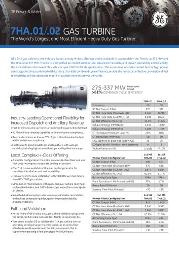
GE10-2 15 ppm combustor0 pages

One of the critical factors in gas turbine design today
is emissions reduction. In mature markets such as
the USA, permits to install new gas turbines
include increasingly restrictive emissions requirements
across a wide range of ambient temperatures and loads.
To meet these requirements, GE Energy has developed
a new combustor for the latest version of its heavy duty
GE 10-2 gas turbine, a 12 MW class, double shaft machine
used predominantly for mechanical drive applications but
also available for power generation. To meet diverse appli-
cation requirements, the turbine is designed for high oper-
ability as well as low emissions.
The new K-1 low emissions combustor ensures the lat-
ter, being capable of guaranteeing the following emissions
levels at loads ranging from 50% to baseload and at ambi-
ent temperatures of -20 T - 100 °F:
• 15 ppmvd (15% 02) for NOx emissions.
• 25 ppmvd (15% 02) for CO.
• 15 ppm for UHC.
Computational fluid dynamics (CFD) tools were used
extensively for studying and designing the overall flame
structure of the new combustor, specifically for investigating
the flame front and the stabilisation capabilities of the new
pilot system, as well as for predicting emissions levels.
Calculated emissions were compared with measurements
obtained by rig and engine tests, producing useful design
information and validation.
Description of the new combustor
While the new K-1 combustor is geometrically derived from
the previous GE 10 model, its flame stabilisation concept
has been revised significantly.
As before, the compressor discharge air is introduced
into the premixing channel via a variable geometry intake.
This device is composed of two cylindrical coaxial parts,
each provided with slots. By rotating around the main com-
bustor axis, these parts make the slots overlap by a vari-
able amount, therefore modulating the airflow and providing
the turbine with excellent operability and turndown
capability.
The main fuel premixes with air and the resulting mix-
ture is introduced into the combustion chamber, generating
a flame that is stabilised by a proper amount of pilot fuel.
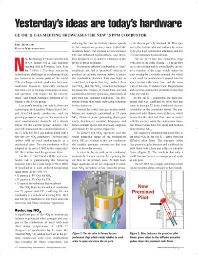
In the old K 1 combustor (Figure 1), this fuel is injected
at the throat and surrounds the main flame over an entire
circumference, so that the main flame is stabilised by a
Meeting the
emissions challenge
Antonio Andreini and Bruno Facchini, University of Florence, Italy, and Antonio Asti and
Gianni Ceccherini, GE Energy, USA, explain how the company's new combustor for its
GE 10-2 gas turbine faces up to emissions restrictions.
HYDROCARBON ENGINEERING AUGUST 2005
41
"