عضویت
عضویت  ورود اعضا
 راهنمای خرید


Humidity Sensors FK80J Humidity-Temperature Sensors TFK80J0 pages
Galltec Mess- und Regeltechnik GmbH
D-71145 Bondorf . Germany
Tel. +49 (0)7457-9453-0 . Fax +49 (0)7457-3758
E-Mail: sensoren@galltec.de . Internet:www.galltec-mela.de
MELA Sensortechnik GmbH
D-07987 Mohlsdorf (Thüringen) . Germany
Tel. +49(0)3661-62704-0 . Fax +49(0)3661-62704-20
E-mail:mela@melasensor.de . Internet: www.galltec-mela.de
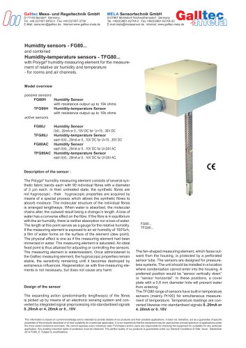
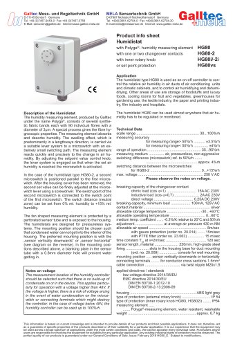
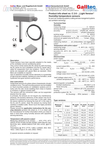
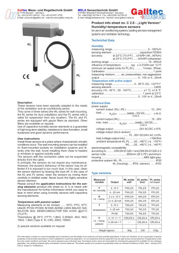
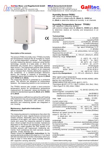
Humidity Sensor FK80J
with capacitive measuring element
with current or voltage output 0...20mA / 0...10VDC or
4...20mA to determine relative air humidity in air channels
Humidity-Temperature Sensor TFK80J
with capacitive measuring element
with current or voltage output, 0...20mA / 0...10VDC or 4...20mA
to determine relative air humidity and temperature in air
channels
Description of the sensors
The sensors FK80J (humidity only) / TFK80J (humidity
and temperature) measure the air humidity by means
of a humidiy-dependant condenser. The capacitive
humidity measuring element, produced using thinfilm
technology, consists of a base plate, on which the
electrodes are housed and a hygroscopic polymer
layer avove it. The hygroscopic polymer layer absorbs
water molecules from the medium to be measured
(air) or releases them, thereby altering the capacity of
the condenser. In a tandem-arranged electronic
device, the change in capacity is processed via
integrated signal preprocessing into signals 0..20mA
or 0..10VDC or 4..20mA.
The measuring element is protected by a protective
guard. The sensors are designed for pressureless
systems - the measuring medium is non-corrosive air.
The TFK80J sensors also contain a semi-conductor
temperature sensor for simultaneous temperature
measurement. Its measured values are likewise converted into standardised signals 0..20mA or 0..10VDC
or 4..20mA
The temperature coefficient as well as the self-heating
of the electronic may vary according to the location and
the application (especially with sensors where
electronic and measuring system are integrated in
one housing.
Maintenance - Application instructions Influence of dirt
The measuring element is maintenance free when the
surrounding air is clean. Agents that are corrosive and
contain solvents, depending upon the type and concentration of the agent, can result in faulty measurements and cause the measuring element to breake
down. Direct sunlight should be avoided. Substances
deposited on the sensor are damaging as they eventually form a water-repellent film (this applies to all
humidity sensors with hygroscopic measuring elements). Such substances are resin aerosols, lacquer
aerosols, smoke deposits etc.
Please consult the application instructions for the
sensing elements (product info sheet no. A 1) or check
with the manufacturer for further information which you
need to bear in mind when using humidity sensors
with capacitive sensing elements.
Technical Data
measuring range humidity.......................................... 0..100%RH
sensing element ................................................... capacitive FE09
accuracy
at 23°C (73,4°F) .............. ±2.0%RH (40...60%RH)
at 23°C (73,4°F) ................... ±2.5%RH (otherwise)
includes linearity and repeatability
temperature effect ......................... typ. less 0,15%RH per °C /°F
operating range.............................................................. 5...95%RH
measuring medium ................. air, pressureless, non-corrosive
Response time (at calm air) ............................................... < 20 s
signal output humidity................0...10V or 0...20mA or 4...20mA
measuring range temperature
.................................................
0...+50°C; 32...+122 °F
.................................................
-10...90°C1); 14...194°F
.................................................
-30...60°C; -22...+140°F
.................................................
0...100°C1); 32...+212°F
sensing element ....................................................... Pt100Class B
accuracy
at 0...10V........................................ ±0.2 K ±0.36 °F
at (0)4...20mA ............................... ±0.3 K ±0.54 °F
operating range ...................................... -30...+80°C (-22...176°F)
signal output temperature ....... 0...10V or 0...20mA or 4...20mA
0ther signal output temperature
NTC; PTC; KTY; LMx35; Pt100; Pt1000; Ni1000; AD592; LM34;
BALKO 1k; SILICON 2k;
SEMICONDUCTOR 559 mVDC @23°C (75°F)
Thermistors @ 25°C (77°F) 1,8k; 2,252k; 3k; 5k; 10k;
1,8k (Type II; III, CSI); 20k; 100k
power supply......................................... 15..30V DC / 24VAC± 10%
electromagnetic compatibility EMC
resistance to interference ............................... EN 50 082-2
interference emission .......................... EN 50 081-2
max. load ........................... RL() =
supply - 10 VDC
0,02 amps
(current output only)
min load (voltage output only) .................................................10 k
power consumption ......................................................... less 5 mA
permissible ambient temperature ...... -40...+80°C (-40...176°F)
at the housing ....... -10....+60°C (14...140°F)
admitted air speed ........................................... 15 m/sec (50 ft/sec)
Minimum air speed (across the sensor):
output 0...10V,2x0...1V...................................................... 0.5m/s
4...20mA,2x0...10V.................................................... 1m/s
2x4...20mA.............................................................. 1.5m/s
probelength .............................................................200mm (7,87")
probe material ....................... aluminium, electrolytically oxidized
for channel mounting ................................ perforation in the case
mounting position............................................................ asyou like
contacting ............................ connecting terminals in the housing
connecting terminal conductor cross sections
........ 1.5mm2 (0,023"2 )
housing..................................................................... polystyrol-ABS
protective system .......................................................................IP64
weight ......................................................... approx. 0.3 kg (0.6 lbs)
1)
please observe working range
"subject to technical modifications"
This information is based on current knowledge and is intended to provide details of our products and their possible applications. It does not, therefore, act as a guarantee of specific properties of
the products described or of their suitability for a particular application. It is our experience that the equipment may be used across a broad spectrum of applications under the most varied conditions
and loads. We cannot appraise every individual case. Purchasers and/or users are responsible for checking the equipment for suitability for any particular application. Any existing industrial rights
of protection must be observed. The perfect quality of our products is guaranteed under our General Conditions of Sale. Issue : August 2008 FK80_E. Subject to modifications.