عضویت
عضویت  ورود اعضا
 راهنمای خرید


H64C Humidity Controller0 pages
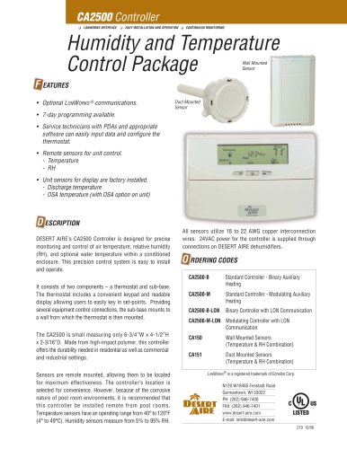
APPLICATION
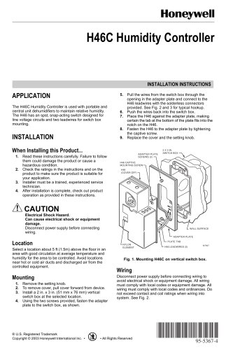
5. Pull the wires from the switch box through the opening in the adapter plate and connect to the H46 leadwires with the solderless connectors provided. See Fig. 2 and 3 for typical hookup. 6. Push the wires back into the switch box. The H46C Humidity Controller is used with portable and central unit dehumidifiers to maintain relative humidity. The H46 has an spst, snap-acting switch designed for line voltage circuits and two leadwires for switch box mounting. 7. Place the H46 against the adapter plate, making certain the tab at the bottom of the plate fits into the notch on the H46. 8. Fasten the H46 to the adapter plate by tightening the captive screw. 9. Replace the cover and the setting knob. >
nnINSTALLATION
nnWhen Installing this Product...
1. Read these instructions carefully. Failure to follow them could damage the product or cause a hazardous condition. 2. Check the ratings in the instructions and on the product to make sure the product is suitable for your application. 3. Installer must be a trained, experienced service technician. >
H46(COVER OFF)H46 CAPTIVEMOUNTING SCREWADAPTER PLATESCREWS (2)2 X 3 IN.SWITCH BOX
NYLONELEMENTH46 LEADWIRES (2)PLATE TABADAPTER PLATEWALL SURFACE 4. After installation is complete, check out product operation as provided in these instructions. >
Electrical Shock Hazard.Can cause electrical shock or equipment damage. Disconnect power supply before connecting wiring. >
nnLocation
Fig. 1. Mounting H46C on vertical switch box. >
M7907 Select a location about 5 ft (1.5m) above the floor in an area with good circulation at average temperature and humidity for the area to be controlled. Avoid locations near hot or cold air ducts and discharged air from the controlled equipment. >
Wiring Mounting
Disconnect power supply before connecting wiring to avoid electrical shock or equipment damage. All wiring must comply with local codes or equipment damage. All wiring must comply with local codes and ordinances. Do not exceed contact and coil ratings when wiring into system. See Fig. 2. 1. Remove the setting knob. 2. To remove cover, pull cover forward from device. 3. Install a 2 in. x 3 in. (51 mm x 76 mm) vertical switch box at the selected location. 4. Using the two screws provided, fasten the adapter plate to the switch box, as shown. >
U.S. Registered TrademarkCopyright Ω 2003 Honeywell International Inc. Օ All Rights Reserved