عضویت
عضویت  ورود اعضا
 راهنمای خرید


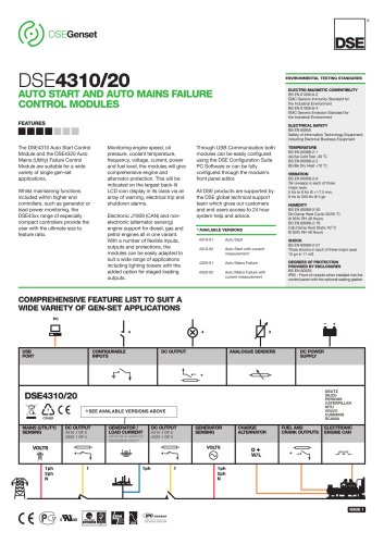
DSE7110-200 pages
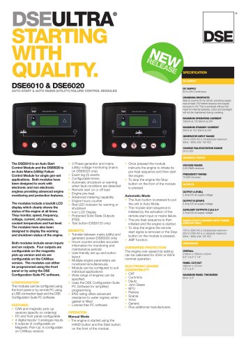
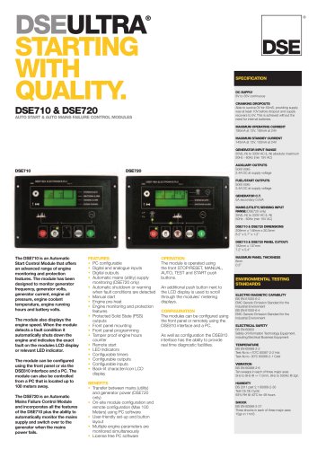
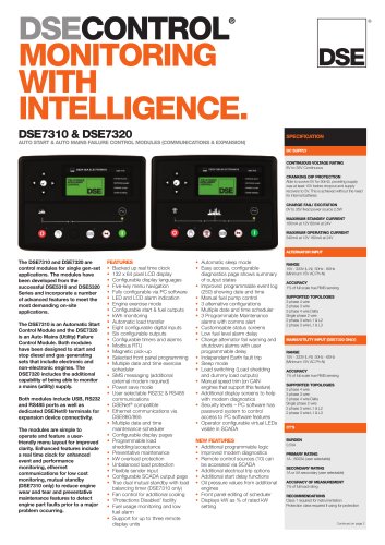
® DSECONTROL®
MONITORING
WITH
INTELLIGENCE.
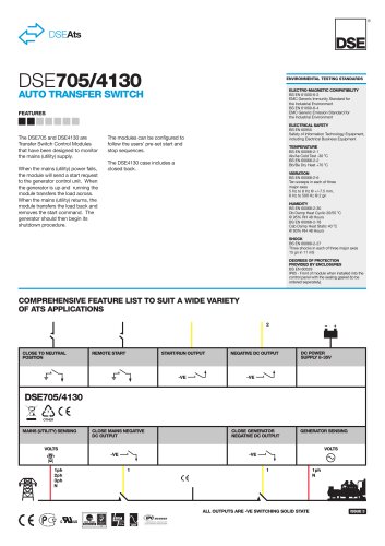
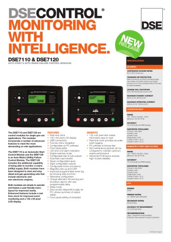
The DSE7110 and DSE7120 are
control modules for single gen-set
applications. The modules
incorporate a number of advanced
features to meet the most
demanding on-site applications.
The DSE7110 is an Automatic Start
Control Module and the DSE7120
is an Auto Mains (Utility) Failure
Control Module. The DSE7120
includes the additional capability
of being able to monitor a mains
(utility) supply. Both modules have
been designed to start and stop
diesel and gas generating sets that
include electronic and
non-electronic engines.
Bothmodules are simple to operate
and feature a user friendlymenu
layout for improved clarity.
Enhanced features include a real
time clock for improved event
monitoring and a 132 x 64 pixel
LCD display.
FEATURES
• Real time clock
• 132 x 64 pixel LCD display
• USB connectivity
• Five key menu navigation
• Configurable via PC software
• Front panel editor
• LED and LCD alarm indication
• Engine exercise mode
• Configurable start & fuel outputs
• Automatic load transfer
• Seven configurable inputs
• Eight configurable outputs
• Configurable timers and alarms
• Magnetic pick-up and CAN
• Improved programmable event log
(5) showing date and time
• Alternative configuration
• Charge alternator fail warning and
shutdown alarms with user
programmable delay
• Sleep mode
• Easy access diagnostics page via
PC, shows summary of output
states
• Front panel editing of scheduler
BENEFITS
• 132 x 64 pixel ratio makes
information easy to read
• Real time clock provides accurate
event logging
• PC software is license free
• Set maintenance periods can be
configured to maintain optimum
engine performance
• Advanced PCB layout ensures
high module reliability
DSE7110 & DSE7120
AUTO START & AUTOMAINS FAILURE CONTROLMODULES
SPECIFICATION
DC SUPPLY
ALTERNATOR INPUT
MAINS/UTILITY INPUT (DSE7120 ONLY)
CONTINUOUS VOLTAGE RATING
8V to 35V Continuous
CRANKING DIP PROTECTION
Able to survive 0V for 50mS, providing supply
was at least 10V before dropout and supply
recovers to 5V. This is achieved without the need
for internal batteries
CHARGE FAIL/ EXCITATION
0V to 35V fixed power source 2.5W
MAXIMUM STANDBY CURRENT
80mA at 12V 40mA at 24V
MAXIMUM OPERATING CURRENT
300mA at 12V 150mA at 24V
RANGE
15V - 333V (L-N) 50Hz - 60Hz
(Minimum 15V AC Ph-N)
ACCURACY
1% of full scale true RMS sensing
SUPPORTED TOPOLOGIES
3 phase 4 wire Delta
3 phase 4 wire
3 phase 3 wire
Single phase 2 wire
2 phase 3 wire L1 & L2
2 phase 3 wire L1 & L3
RANGE
15V - 333V (L-N) 50Hz - 60Hz
(Minimum 15V AC Ph-N)
ACCURACY
1% of full scale true RMS sensing
SUPPORTED TOPOLOGIES
3 phase 4 wire Delta
3 phase 4 wire
3 phase 3 wire
Single phase 2 wire
2 phase 3 wire L1 & L2
2 phase 3 wire L1 & L3
CT’S
BURDEN
0.5VA
PRIMARY RATING
1A - 8000A (user selectable)
SECONDARY RATING
5A secondary
ACCURACY OFMEASUREMENT
1% of full load rating
RECOMMENDATIONS
Class 1 required for instrumentation
Protection class required if using for protection
Continued on page 2
NEW RELEASE