عضویت
عضویت  ورود اعضا
 راهنمای خرید


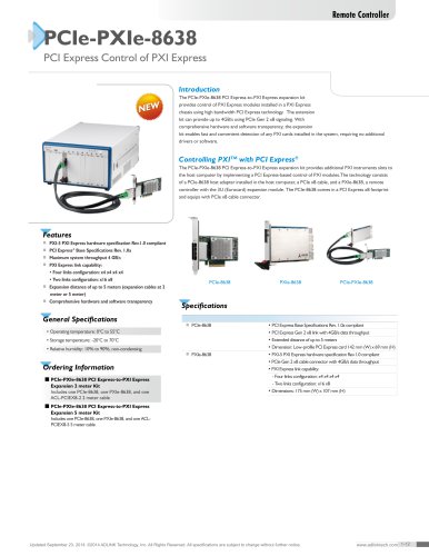
PCI/PXI-95270 pages
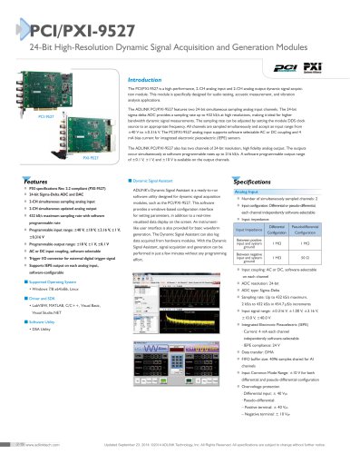
PCI/PXI-9527
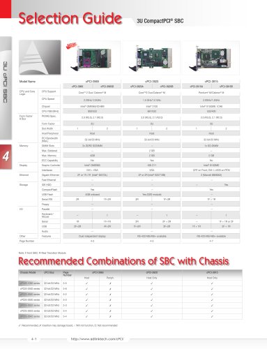
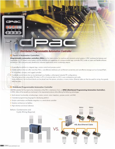
24-Bit High-Resolution Dynamic Signal Acquisition and Generation Modules
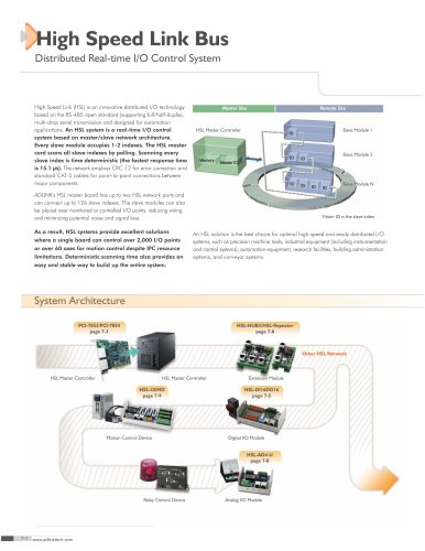
Introduction
The PCI/PXI-9527 is a high-performance, 2-CH analog input and 2-CH analog output dynamic signal acquisition module. This module is specifically designed for audio testing, acoustic measurement, and vibration
analysis applications.
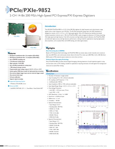
The ADLINK PCI/PXI-9527 features two 24-bit simultaneous sampling analog input channels. The 24-bit
sigma-delta ADC provides a sampling rate up to 432 kS/s at high resolutions, making it ideal for higher
bandwidth dynamic signal measurements. The sampling rate can be adjusted by setting the module DDS clock
source to an appropriate frequency. All channels are sampled simultaneously and accept an input range from
±40 V to ±0.316 V. The PCI/PXI-9527 analog input supports software selectable AC or DC coupling and 4
mA bias current for integrated electronic piezoelectric (IEPE) sensors.
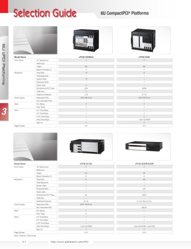
PCI-9527
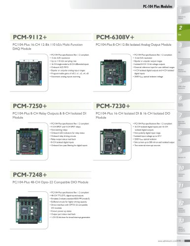
The ADLINK PCI/PXI-9527 also has two channels of 24-bit resolution, high fidelity analog output. The outputs
occur simultaneously at software programmable rates up to 216 kS/s. A software programmable output range
of ±0.1 V, ±1 V, and ±10 V is available on the output channels.
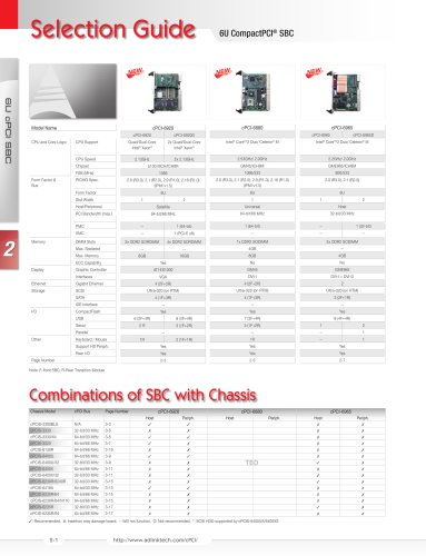
PXI-9527
Features
■tDynamic Signal Assistant
■t
PXI specifications Rev. 2.2 compliant (PXI-9527)
■t 24-bit Sigma-Delta ADC and DAC
software utility designed for dynamic signal acquisition t
■t
2-CH simultaneous sampling analog input
modules, such as the PCI/PXI-9527. This software t
■t
2-CH simultaneous updated analog output
provides a windows-based configuration interface t
Specifications
ADLINK’s Dynamic Signal Assistant is a ready-to-run t
■t
432 kS/s maximum sampling rate with software
for setting parameters, in addition to a real-time t
programmable rate
visualized data display on the screen. An instrument-t
■t
Programmable input range: ±40 V, ±10 V, ±3.16 V, ±1 V, t
±0.316 V
■t
Programmable output range: ±10 V, ±1 V, ±0.1 V
AC or DC input coupling, software selectable
Signal Assistant, signal acquisition and generation can be t
performed in just a few minutes without any programming t
■t
Trigger I/O connector for external digital trigger signal
■t
Supports IEPE output on each analog input,
Input configuration: Differential or pseudo-differential, t
tt each channel independently software-selectable
data acquired from hardware modules. With the Dynamic t
■t
Number of simultaneously sampled channels: 2
■t
generation. The Dynamic Signal Assistant can also log t
■t
like user interface is also provided for basic waveform t
Analog Input
t
tsoftware-configurable
■t
Input impedance:
Differential
Pseudodifferential
Configuration
Configuration
Between positive
input and system
ground
1 MΩ
1 MΩ
Between negative
input and system
ground
1 MΩ
50 Ω
Input Impedance
teffort.
t
■t
Input coupling: AC or DC, software-selectable t
on each channel
■tSupported Operating System
■t
ADC resolution: 24-bit
• Windows 7/8 x64/x86, Linux
■t
ADC type: Sigma-Delta
■tDriver and SDK
■t
Sampling rate: Up to 432 kS/s maximum,
tt 2 kS/s to 432 kS/s in 454.7 µS/s increments
• LabVIEW, MATLAB, C/C++, Visual Basic,
Visual Studio.NET
■tSoftware Utility
t
• DSA Utility
■t
Input signal range: ±0.316 V, ±1.00 V, ±3.16 V, t
tt ±10.0 V, ±40.0 V
t
■t
Integrated Electronic Piezoelectric (IEPE)
tt · Current: 4 mA each channel
tt
independently software-selectable
tt · IEPE compliance: 24 V
t
■t
Data transfer: DMA
■t
FIFO buffer size: 4096 samples shared for AI tt
tt channels
t
■t
Input Common Mode Range: ±10 V for both tt
tt differential and pseudo-differential configuration
t
■t
Overvoltage protection
tt · Differential input: ± 40 Vpk
tt · Pseudo-differential:
tt – Positive terminal: ± 40 Vpk
tt – Negative terminal: ± 10 Vpk
2-19 www.adlinktech.com
Updated September 23, 2014. ©2014 ADLINK Technology, Inc. All Rights Reserved. All specifications are subject to change without further notice.
"