عضویت
عضویت  ورود اعضا
 راهنمای خرید


How to Design the Optimum Hinge0 pages
How to Design the Optimum Hinge
by Christie L. Jones, Market Development Manager
SPIROL International Corporation, Danielson, CT, U.S.A.
WHITE PAPER
There are two primary types of hinges:
1)tA free fit hinge has little to no friction or drag when the latch or handle is rotated.
Hinge components are “free” to rotate independent of one another.
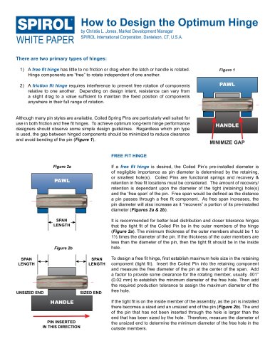
Figure 1
2)tA friction fit hinge requires interference to prevent free rotation of components
relative to one another. Depending on design intent, resistance can vary from
a slight drag to a value sufficient to maintain the fixed position of components
anywhere in their full range of rotation.
PAWL
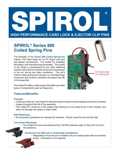
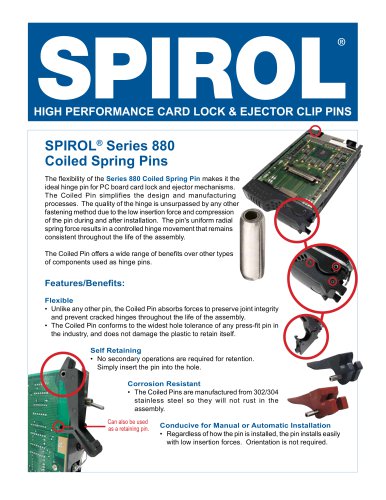
Although many pin styles are available, Coiled Spring Pins are particularly well suited for
use in both friction and free fit hinges. To achieve optimum long-term hinge performance
designers should observe some simple design guidelines. Regardless which pin type
is used, the gap between hinged components should be minimized to reduce clearance
and avoid bending of the pin (Figure 1).
HANDLE
MINIMIZE GAP
FREE FIT HINGE
If a free fit hinge is desired, the Coiled Pin’s pre-installed diameter is
of negligible importance as pin diameter is determined by the retaining,
or smallest hole(s). Coiled Pins are functional springs and recovery &
retention in free fit locations must be considered. The amount of recovery/
retention is dependant upon the diameter of the tight (retaining) hole(s)
and the ‘free span’ of the pin. Free span would be defined as the distance
a pin passes through a free fit component. As free span increases, the
pin diameter will also increase as it “recovers” a portion of its pre-installed
diameter (Figures 2a & 2b).
Figure 2a
PAWL
It is recommended for better load distribution and closer tolerance hinges
that the tight fit of the Coiled Pin be in the outer members of the hinge
(Figure 2a). The minimum thickness of the outer members should be 1 to
1½ times the diameter of the pin. If the thickness of the outer members are
less than the diameter of the pin, then the tight fit should be in the inside
hole.
SPAN
LENGTH
Figure 2b
SPAN
LENGTH
SPAN
LENGTH
UNSIZED END
SIZED END
HANDLE
PIN INSERTED
IN THIS DIRECTION
To design a free fit hinge, first establish maximum hole size in the retaining
component (tight fit). Insert the Coiled Pin into the retaining component
and measure the free diameter of the pin at the center of the span. Add
a factor to provide some clearance for the rotating member, usually .001”
(0.02 mm) to establish the minimum diameter of the free hole. Then add
the required production tolerance to assign the maximum diameter of the
free hole.
If the tight fit is on the inside member of the assembly, as the pin is installed
there becomes a sized and an unsized end of the pin (Figure 2b). The end
of the pin that has not been inserted through the hole is larger than the
end that has been sized by the hole. Therefore, measure the diameter of
the unsized end to determine the minimum diameter of the free hole in the
outside members.