عضویت
عضویت  ورود اعضا
 راهنمای خرید


TE1500 pages
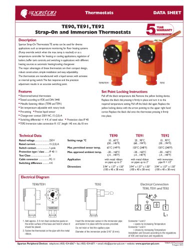
Thermostats
DATA SHEET
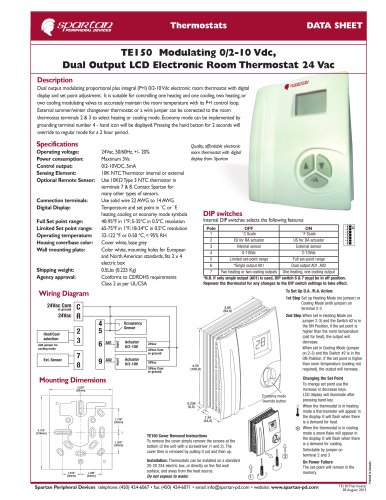
TE150 Modulating 0/2-10 Vdc,
Dual Output LCD Electronic Room Thermostat 24 Vac
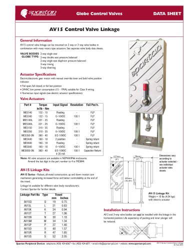
Description
Dual output modulating proportional plus integral (P+I) 0/2-10 Vdc electronic room thermostat with digital
display and set point adjustment. It is suitable for controlling one heating and one cooling, two heating, or
two cooling modulating valves to accurately maintain the room temperature with its P+I control loop.
External summer/winter changeover thermostat or a wire jumper can be connected to the room
thermostat terminals 2 & 3 to select heating or cooling mode. Economy mode can be implemented by
grounding terminal number 4 - hand icon will be displayed. Pressing the hand button for 2 seconds will
override to regular mode for a 2 hour period.
Specifications
Quality, affordable electronic
Connection terminals:
Digital Display:
Full Set point range:
Limited Set point range:
Operating temperature:
Housing cover/base color:
Wall mounting plate:
Shipping weight:
Agency approval:
24Vac, 50/60Hz, +/- 20%
room thermostat with digital
display from Spartan
Maximum 3Va
0/2-10VDC, 5mA
10K NTC Thermistor internal or external
Use 10KΩ Type 3 NTC thermistor in
terminals 7 & 8. Contact Spartan for
many other types of sensors.
Use solid wire 22 AWG to 14 AWG
Temperature and set point in ˚C or ˚F,
heating, cooling or economy mode symbols
DIP switches
Internal DIP switches selects the following features
40-95ºF in 1ºF; 5-35ºC in 0.5ºC resolution
Pole
OFF
ON
65-75ºF in 1ºF; 18-24ºC in 0.5ºC resolution
1
˚ C Scale
˚ F Scale
32-122 ºF or 0-50 ºC, < 95% RH
2
EU for RA actuator
US for DA actuator
Cover white, base grey
3
Internal sensor
External sensor
Color white, mounting holes for European
4
0-10Vdc
2-10Vdc
and North American standards, fits 2 x 4
5
Limited set-point range
Full set-point range
electric box
6
*Single output A01
Dual output A01, A02
0.5Lbs (0.225 Kg)
7
Two heating or two cooling outputs One heating, one cooling output
Conforms to CE/ROHS requirements
*N.B. If only single output (A01) is used, DIP switch 6 & 7 must be in off position.
Repower the thermostat for any changes to the DIP switch settings to take effect.
Class 2 as per UL/CSA
To Set Up D.A. /R.A. Action:
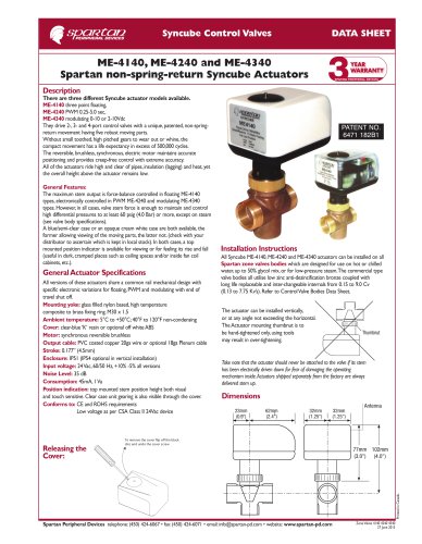
Wiring Diagram
24Vac
C
R
4
5
2
3
Heat/Cool
selection
Add jumper for
cooling mode
6
7
8
Ext. Sensor
9
Occupancy
Sensor
A01
A02
Input
or ground
Actuator
0/2-10V
Input
24Vac Com
1st Step Set up Heating Mode (no jumper) or
Cooling Mode (with jumper) on
terminal 2-3
Actuator
0/2-10V
24Vac
24Vac Com
or ground
24Vac
24Vac Com
or ground
2nd Step When set in Heating Mode (no
jumper 2-3) and the Switch #2 is in
the ON Position, if the set point is
higher than the room temperature
(call for heat), the output will
decrease.
When set in Cooling Mode (jumper
on 2-3) and the Switch #2 is in the
ON Position, if the set point is higher
than room temperature (cooling not
required), the output will increase.
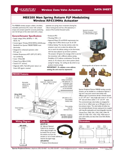
Mounting Dimensions
3.520”
[89mm]
Economy mode
override button
1.376”
[35mm]
?
4.178”
[106mm]
1.200”
[30mm]
1.010”
[26mm]
1.188”
[30mm]
TE150 Cover Removal Instructions
To remove the cover simply remove the screws at the
bottom of the unit with a screwdriver (1 and 2). The
cover then is removed by pulling it out and then up.
Installation: Thermostats can be installed on a standard
20-20 2X4 electric box, or directly on the flat wall
surface, and away from the heat source.
Do not expose to water.
Changing the Set Point
To change set point use the
increase or decrease keys.
LCD display will illuminate after
pressing hand key.
When the thermostat is in heating
mode a thermometer will appear in
the display. It will flash when there
is a demand for heat.
When the thermostat is in cooling
mode a snow flake will appear in
the display. It will flash when there
is a demand for cooling.
Selectable by jumper on
terminal 2 and 3
On Power Failure
The set-point will remain in the
memory.
Spartan Peripheral Devices telephone: (450) 424-6067 • fax: (450) 424-6071 • email: info@spartan-pd.com • website: www.spartan-pd.com
TE150Thermostat
28 August 2013
Printed in Canada
Operating voltage:
Power consumption:
Control output:
Sensing Element:
Optional Remote Sensor: