عضویت
عضویت  ورود اعضا
 راهنمای خرید


TE1510 pages

Thermostats
DATA SHEET
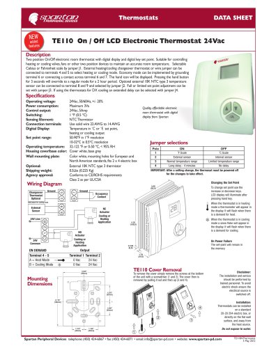
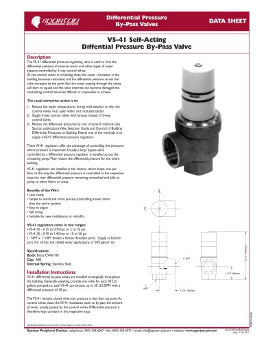
TE151 Modulating 0-10Vdc, LCD Electronic Thermostat
with single speed fan switch 24Vac
Description
Modulating proportional plus integral (P+I) 0-10 Vdc electronic room thermostat with digital
display and set point adjustment. It is suitable for controlling a single speed fan as well as
controlling a single heating or cooling modulating valve to maintain the room temperature. An
On/ Auto Switch on the thermostat cover will switch the fan On. In Auto position, it will cycle
the fan from the room temperature if reaching the set point, this cycle is for maximum energy
saving. Heating/Off/Cooling switch on the thermostat cover will select heating or cooling mode.
Jumper J2 set to U.S. or E..U. setting will reverse the 0-10Vdc signal. Selectable between ºC and
ºF scales by jumper on PCB.
Specifications
Operating voltage:
Power consumption:
Control output:
Fan Switch:
Sensing Element:
Connection terminals:
Digital Display:
Set point range:
Operating temperature:
Housing cover/base color:
Wall mounting plate:
Shipping weight:
Agency approval:
24Vac, 50/60Hz, +/- 20%
Maximum 3Va
0-10Vdc, 30mA
1A, 24Vac
NTC Thermistor
Use solid wire 22 AWG to 14 AWG
Temperature in ˚C or ˚F, set point,
heating or cooling output
40-95ºF in 1ºF resolution
5-35ºC in 0.5ºC resolution
32-122 ºF or 0-50 ºC, < 95% RH
Cover white, base grey
Color white, mounting holes for
European and North American
standards, fits 2 x 4 electric box
0.5Lbs (0.225 Kg)
Heat
Conforms to CE requirements
Off
Class 2 as per UL/CSA
Cool
Quality, affordable electronic
room thermostat with digital
display from Spartan
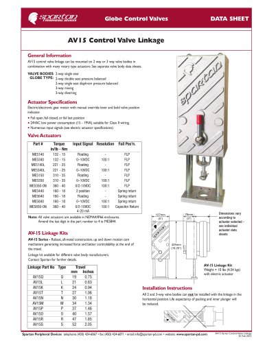
Changing the Set Point
To change set point use the
increase or decrease keys.
LCD display will illuminate after
pressing hand key.
When the thermostat is in heating
mode a thermometer will appear
in the display. It will flash when
there is a demand for heat.
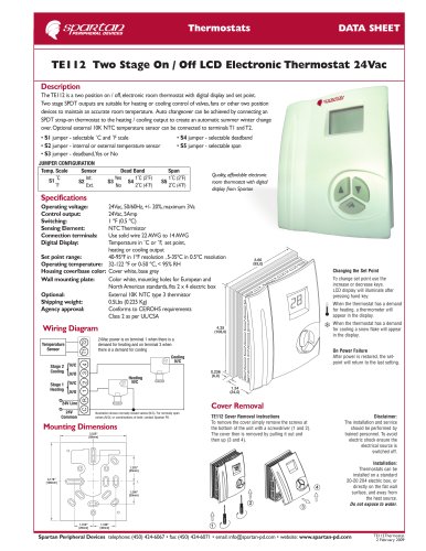
Wiring Diagram
1
6
Red
White
When the thermostat is in cooling
mode a snow flake will appear in
the display. It will flash when
there is a demand for cooling.
On Power Failure
The set-point will return to the
factory default setting 75˚F/24˚C.
Fan Relay
L N
24VAC
c
Black
0-10VDC
Neutral or Ground
Fan Switch
On
Auto
Line
Thermostat
Terminal
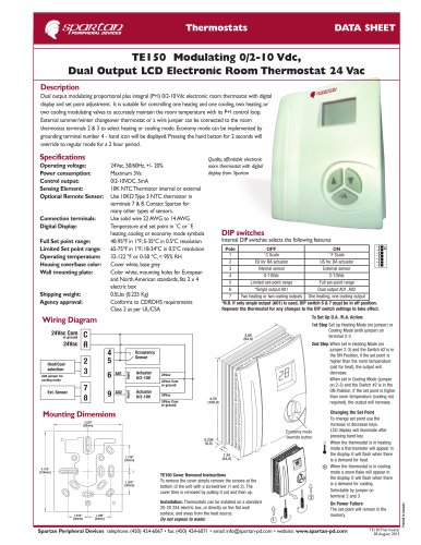
Mounting Dimensions
Cover Removal
3.520”
[89mm]
TE120 Cover Removal Instructions
To remove the cover simply remove the screws at
the bottom of the unit with a screwdriver (1 and 2).
The cover then is removed by pulling it out and
then up (3 and 4).
1.376”
[35mm]
4.178”
[106mm]
1.200”
[30mm]
1.010”
[26mm]
Disclaimer:
The installation and service
should be performed by
trained personnel. To avoid
electric shock ensure the
electrical source is
switched off.
Installation:
Thermostats can be
installed on a standard
20-20 2X4 electric box, or
directly on the flat wall
surface, and away from
the heat source.
Do not expose to water.
1.188”
[30mm]
Spartan Peripheral Devices telephone: (450) 424-6067 • fax: (450) 424-6071 • email: info@spartan-pd.com • website: www.spartan-pd.com
TE151Thermostat
2 May 2008