عضویت
عضویت  ورود اعضا
 راهنمای خرید


CALOMAT 620 pages

© Siemens AG 2015
Continuous Gas Analyzers, extractive
CALOMAT 62
1
General information
■ Overview
■ Design
19" rack unit
• With 4HE for installation
- in hinged frame
- in cabinets with or without telescope rails
- With closed or flow-type reference chambers
• Front plate for service purposes can be pivoted down
(laptop connection)
• IP20 degree of protection, with purging gas connection
• Internal gas routes: Pipe made of stainless steel
(mat. no. 1.4571)
• Gas connections for sample gas inlet and outlet and for reference gas: Internal thread 1/8" – 27 NPT
• Purging gas connections: Pipe diameter 6 mm or 1/4"
• With closed or flow-type reference chambers
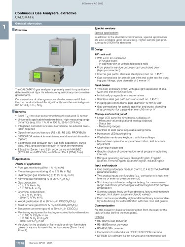
The CALOMAT 62 gas analyzer is primarily used for quantitative
determination of one gas component (e.g. H2, N2, Cl2, HCl, NH3)
in binary or quasi-binary gas mixtures.
The CALOMAT 62 is specially designed for use in corrosive gas
mixtures.
■ Benefits
• Universally applicable hardware basis
• Integrated correction of cross-interference, no external calculation required
• Open interface architecture (RS 485, RS 232, PROFIBUS)
• SIPROM GA network for maintenance and servicing information (option)
• Electronics and analyzer unit: gas-tight isolation, purging is
possible, IP65, long service life even in harsh environments
(field device)
■ Application
Fields of application
• Chlorine-alkali electrolysis
• Metallurgy (steel production and processing)
• H2 measurement in LNG (Liquefied Natural Gas) process
• Ammonia synthesis
• Fertilizer production
• Petrochemicals
Special versions
Special applications
In addition to the standard combinations, special applications
are also available upon request (e.g. higher sample gas pressure up to 2 000 hPa absolute).
1/198
Siemens AP 01 · 2015
Field device
• Two-door enclosure (IP65) for wall mounting with gas-tight
separation of analyzer and electronic parts, purgeable
• Individually purgeable enclosure halves
• Gas path with screw pipe connection made of stainless steel
(mat. no. 1.4571), or Hastelloy C22
• Purging gas connections: Pipe diameter 10 mm or 3/8"
• Gas connections for sample gas inlet and outlet and for reference gas: Internal thread 1/8" – 27 NPT
• With closed or flow-type reference chambers
Display and control panel
• Large LCD field for simultaneous display of:
- Measured value (digital and analog displays)
- Status bar
- Measuring ranges
• Contrast of the LCD field adjustable via the menu
• Permanent LED backlighting
• Washable membrane keyboard with five softkeys
• Menu-driven operator control for parameterization, test functions, adjustment
• Operator support in plain text
• Graphical display of the concentration progression; time intervals parameterizable
• Bilingual operating software German/English,
English/Spanish, French/English, Spanish/English,
Italian/English
Input and outputs
• One analog output per medium (from 0, 2, 4 to 20 mA; NAMUR
parameterizable)
• Two analog inputs configurable (e.g. correction of cross-interference or external pressure sensor)
• Six binary inputs freely configurable (e.g. measurement range
changeover, processing of external signals from the sample
preparation)
• Six relay outputs, freely configurable (e.g. failure, maintenance request, threshold alarm, external magnetic valves)
• Each can be expanded by eight additional binary inputs and
relay outputs (e.g. for autocalibration with max. four test
gases)