عضویت
عضویت  ورود اعضا
 راهنمای خرید


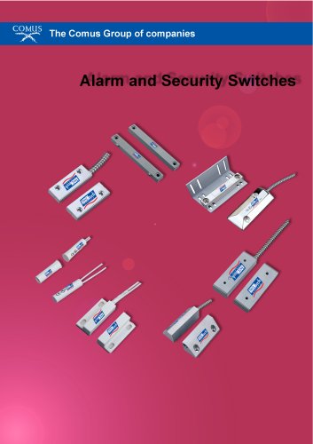
Housed & SMD Reed Switches0 pages
S E N S I N G
T H E
W O R L D ' S
N E E D S
The Comus International group of companies consists of:
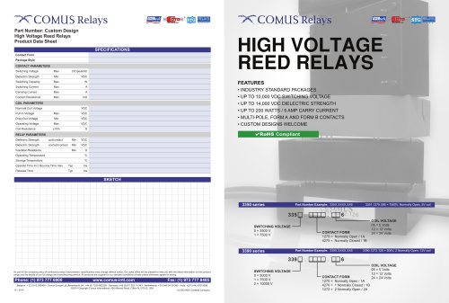
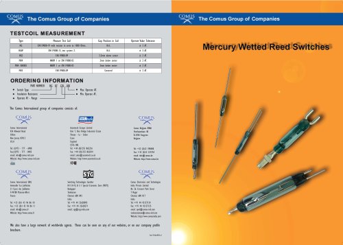
DESCRIPTION
Reed Switches consist of two or three ferromagnetic blades (or reeds) hermetically sealed inside a glass envelope.The construction ensures
protection from the external environment. Three types are available: Form A (normally open), Form B (normally closed), and Form C
(changeover). Form B reed switches are obtained by two methods: By using normally closed blade of a Form C switch, or, by using a Form
A switch, and biasing the contacts closed using a small block magnet.The switch is then able to re-open by the use of another stronger
external magnet of opposite polarity. Sensitivity of a reed switch is measured in ampere turns (A.T.) and it should be noted that lower
switch (A.T.) ratings are more sensitive as they require less magnetic field strength to operate them.Various voltage and current switching
levels are available and contact plating materials can be varied to accommodate specific types of load.
OPERATION
Lamp Loads
Reed Switches are operated by a magnetic field, via a magnet or a current carrying coil.
When the field is removed the switch reverts to its previous state.
Operation by a magnet can be achieved in a large variety of ways, either moving the
magnet toward and away from the reed either perpendicularly, or parallel to the glass.
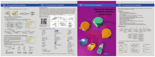
Reed Switches are used in a variety of Comus Group products including Proximity Switches,
Float Switches and Reed Relays. They are now available in housed packages affording
protection from damage and Surface Mount styles.
With lamp load applications it is important to note that cold lamp filaments have a
resistance 10 times smaller than already glowing filaments. This means that when being
turned on, the lamp filament experiences a current flow 10 times greater than when already
glowing. This high inrush current can be reduced to an acceptable level through the use of
a series of current-limiting resistors. Another possibility is the parallel switching of a resistor
across the switch. This allows just enough current to flow to the filament to keep it warm,
yet not enough to make it glow.
Actuation of Reed Switches with a Permanent Magnet
(Examples of switching with the use of a moving magnet.)
Examples of switching through rotational movement.
Direct Actuation:
Comus International
454 Allwood Road
Clifton
New Jersey 07012
U.S.A
Tel: (1)973 - 777 - 6900
Fax:(1)973 - 777 - 8405
email: info@comus-intl.com
Website: http://www.comus-intl.com
Comus Europe Limited
Unit 7, Rice Bridge Industrial Estate
Thorpe - Le - Soken
Essex
England
CO16 0HL
Tel: +44 (0)1255 862236
Fax: +44 (0)1255 862014
email: sales@comuseurope.co.uk
Website: http://www.comuseurope.co.uk
Open
A magnet moved perpendicularly towards and
away from a Reed Switch turns it off and
on once.
Comus Belgium BVBA
Overhaamlaan 40
B-3700 Tongeren
Belgium
Closed
Open
Magnet
A magnet swung towards and away from
a Reed Switch operates it once.
CONTACT PROTECTION
Open
Closed
Open
Ring Magnet
Lamp load with parallel or current limiting resistor
across the switch
Cutting and Bending:
As the Reed Switch blades are part of the magnetic circuit of a Reed Switch shortening the
leads results in increased pull-in and drop-out values.
Comus Technology BV
Jan Campertstraat 11
6416 SG Heerlen
The Netherlands
Switching Technologies Gunther
B-9, B-10, & C-1 Special Economic Zone (MEPZ)
Kadapperi
Tambaram
Chennai 600 045
India
Tel: +31(0)45-54.39.345
Fax: +31(0)45-54.27.216
email: info@comus-intl.com
Website: http://www.dry-reeds.com
Capacitive Loads
Unlike inductive loads, capacitive and lamp loads are prone to high inrush currents which
can lead to faulty operation and even contact welding.
When switching charged capacitors (including cable capacitance) a sudden unloading can
occur, the intensity of which is determined by the capacity and length of the connecting
leads to the switch. This inrush peak can be reduced by a series of resistors. The value is
dependent on the particular application but should be as high as possible to ensure that the
inrush current is within the allowable limits.
In General:
Comus Electronics and Technologies
India Private Limited
2nd Floor, 31/33, Anjugam Nagar, 2nd
Street, Ashok Nagar, Jaferkhanpet,
Chennai 600083
Tamil Nadu, India
Tel: +(91)-(44)-42023510
Fax: +(91)-(44)-22628198
email: info@comus-intl.com
Website: http://www.comusindia.com
Closed
Magnet
With the stationary arrangement of a Reed Switch and magnet, the contact Reeds are closed.
Should the magnetic field be diverted away from the Reed Switch by a shield of
ferromagnetic material placed between the switch and the magnet, the contacts will open.
When the shield is removed, the contact Reeds become magnetically actuated and close.
Magnet
Closed
A ring magnet moved parallel to a Reed
Switchs’ axis operates it from one to three
times.
Inductive Loads
Closed
Indirect Actuation: Shielding
Magnet
Tel: +32 (0)12 390400
Fax: +32 (0)12 235754
email: info@comus.be
Website: http://www.comus.be
Magnet
Open
A magnet moved parallel to a Reed Switch
operates it from one to three times.
Open
A reverse voltage is generated by stored energy in an inductive load when the reed contacts
open. This voltage can reach very high levels and is capable of damaging the contacts. An RC
network may be used as shown below to give protection.
Rotation:
Closed
Magnet
Magnetic shield
Pull-in Sensitivity:
The given pull-in sensitivity of the Reed Switch has a test equipment tolerance of ± 2 AT.
For all Reed Switches the standard pull-in sensitivity is given in the table.
Other pull-in sensitivities are available on request.
Contact Form A
Contact Form B
Life Expectancy:
The life expectancy of a reed switch is dependent upon the load being switched. At
maximum rated loads life expectancy is approximately 106 switching cycles. Lower load
ratings can increase the life expectancy up to 5x10⁸ operations. The mechanical life
expectancy can reach at least 109 operations. Through the switching of inductive, capacitive,
and lamps loads, the life expectancy is considerably reduced due to exceeding the specified
maximum current.
Magnet Biasing Contact
Contact Form B or C
Normally Closed Contact (Form B)
RELAYS -UNLIMITED.com
COMPUTER COMPONENTS INC.
When cutting or bending Reed Switches, it is important that the glass body should not be
damaged. Therefore, the cutting or bending point should be no closer than 3mm (.118) to
the glass body.
Computer Components Inc.
18-B Kripes Rd.
East Granby
Connecticut 06026
U.S.A
Normally Open Contact (Form C)
Tel: (1)401 - 228 - 5459
The above diagram illustrates a resistor/capacitor network for protecting a Reed Switch
against high inrush currents. R1 and/or R2 are used depending upon circuit conditions.
All dimensions are nominal, in millimeters unless otherwise stated. If further information is required, individual datasheets are available on our websites, and on CD.
As part of the group’s policy of continued product improvement, specifications may change without notice. Our sales office will be pleased to help you with the latest information on our products.
email: bbiernacki@relays-unlimited.com
Website: http://www.relays-unlimited.com
We also have a large network of worldwide agents. These can be seen on any of our websites, or on our company profile brochure.
Com/1/Oct14/Iss.4
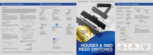
HOUSED & SMD
REED SWITCHES
From the Comus Group of Companies
All dimensions are nominal, in millimeters unless otherwise stated. If further information is required, individual datasheets are available on our websites, and on CD.
As part of the group’s policy of continued product improvement, specifications may change without notice. Our sales office will be pleased to help you with the latest information on our products.