عضویت
عضویت  ورود اعضا
 راهنمای خرید


PIN CLAMPS0 pages

UNIVER S.p.A.
Headquarter
20128 Milano
Via Eraclito, 31
Tel. +39 02 25298.1
Fax +39 02 2575254
info@univer-group.com
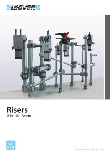
www.univer-group.com
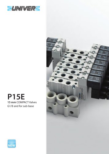
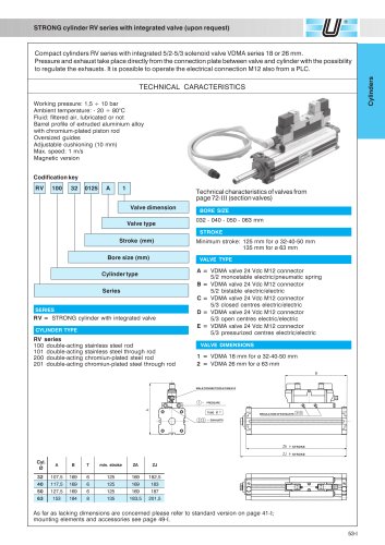
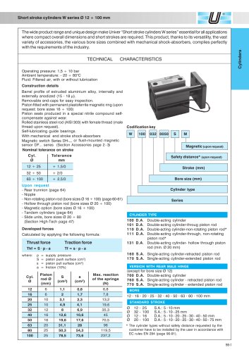
Pneumatic pin clamps
The handling, positioning as well as the maintenance operations have to be carried out by observing all conditions which guarantee the
security of the staff and only by authorized personnel. The residual risks regarding the sole maintenance phase consist in the squashing
of the upper parts of the operator’s body against the unit. As a preventive measure an appropriate signalling or an adequate security
system placed near the dangerous areas and which have to be installed by the user will alert the operator.
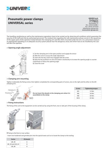
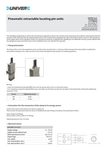
> Fixing instructions
The fixing of the unit to the equipment can be carried out by using the front or rear part of the housing of the clamp. Before installing the
retractable locating pin unit make sure that it hasn’t been damaged during transport or handling operations.
Fixing
- Insert two hardened and grinded Ø8H7 pins into the special seats such as to locate the clamp
- Fix it steadily by using the indicated M8 screws, and make sure that they are about 12 mm deep in the thread holes, limiting the tightening
torque by 15 Nm
> Instructions for the connection of the clamp to its energy source
Connect the sensor of the clamp to its electric supply unit.
Then connect the pneumatic tube by means of suitable pneumatic fittings according to the specification below:
LUP63 series G1/8” fittings
LSP50G, LSP50U, LTP50T series G1/4” fittings
Operating pressure from 4 to 8 bar
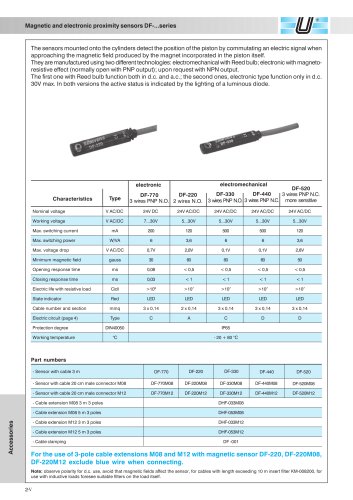
> Electrical sensor
ELECTRIC FEATURES
Supply voltage
Supply current without load
Rated operational current
Output logic
Led- supply
Led- close position- pin 2
Led- open position- pin 4
10 ÷ 30 Vdc
< 20 mA
Max 30 mA
PNP N.O.
green
red
yellow