عضویت
عضویت  ورود اعضا
 راهنمای خرید


XDAS-V2 2.5mm pitch0 pages

X-ray data acquisition dual energy
XDAS-V2 2.5mm pitch
1
SENS-TECH
SENSOR TECHNOLOGIES
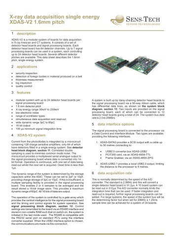
description
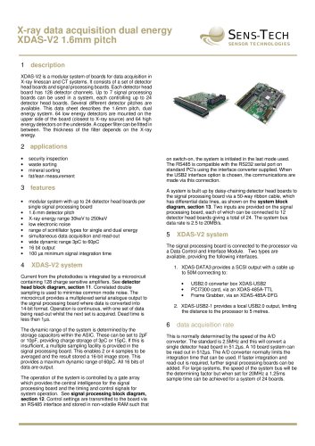
XDAS-V2 is a modular system of boards for data acquisition
in X-ray linescan and CT systems. It consists of a set of
detector head boards and signal processing boards. Each
detector head board has 128 detector channels. Up to 7
signal processing boards can be used in a system, each
controlling up to 24 detector head boards. Several different
detector pitches are available. This data sheet describes the
2.5 mm pitch, single or dual energy system. A single energy
system requires detectors to be fitted only to the upper side of
the board.
2 applications
·
baggage inspection, large tunnel size
·
whole body security inspection
·
thickness measurement
·
quality control
3
features
·
modular system with up to 24 detector head boards per
signal processing board
· mm detector pitch, other designs to special order
2.5
· electronic noise
low
·
range of scintillator types
·
simultaneous data acquisition and read-out
· dynamic range 3pC to 60pC
wide
· bit output
16
·
100µs minimum signal integration time
4
XDAS-HE system
Current from the photodiodes is integrated by a microcircuit
containing 128 charge sensitive amplifiers. See detector
head block diagram, section 11. Correlated double
sampling is used to minimise common mode noise. The
microcircuit provides a multiplexed serial analogue output to
the signal processing board where data is converted into 14bit format. Operation is continuous, with one set of data being
read-out whilst the next set is acquired. Dead time is less than
1µs.
The dynamic range of the system is determined by the
storage capacitors within the ASIC. These can be set to 2pF
or 10pF, providing charge storage of 3pC or 15pC. If this is
insufficient, a multiple sampling facility is provided in the
signal processing board. This enables 2 or 4 samples to be
averaged and the result stored a 16-bit image store. This
provides a maximum dynamic range of 60pC. All 16 bits of
data are output.
The operation of the system is controlled by a gate array
which provides the central intelligence for the signal
processing board and the timing and control signals for
system operation. See signal processing block diagram,
section 12. Control settings are transmitted to the board via
an RS485 interface and stored in non-volatile RAM such that
on switch-on, the system is initiated in the last mode used.
The RS485 is compatible with the RS232 serial port on
standard PC's using the interface converter supplied. When
the USB2 interface option is chosen, the communications are
made via this connection.
A system is built up by daisy-chaining detector head boards to
the signal processing board via a 50-way ribbon cable, which
has differential data lines, as shown on the system block
diagram, section 13. Two inputs are provided on the signal
processing board, each of which can be connected to 12
detector head boards giving a total of 24. The system bus
data rate is 2.5 to 20MB/s.
5
data interface options
The signal processing board is connected to the processor via
a Data Control and Interface Module. Two types are
available, providing the following interfaces.
1. XDAS-DATA3 provides a SCSI output with a cable up
to 50M connecting to:
·
USB2.0 converter box XDAS-USB2
·
PCI7300 card, via an XDAS-485A-TTL
·
Frame Grabber, via an XDAS-485A-DFG
2. XDAS-USB2-1 provides a local USB2.0 output, limiting
the distance to the processor to 5 metres
6
data acquisition rate
This is normally determined by the speed of the A/D
converter. The standard is 2.5MHz and this will convert a
single detector head board in 51.2µs. A 10 board system can
be read out in 512µs. The A/D converter normally limits the
integration time that can be used. If faster integration and
read-out is required, further signal processing boards can be
added. For large systems, the speed of the system bus will be
the determining factor but when set for 20MHz a 1.25ms
sample time can be achieved for a system of 24 boards.