عضویت
عضویت  ورود اعضا
 راهنمای خرید


PS18180 pages

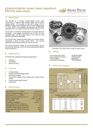
photomultiplier power base (negative)
PS1818 data sheet
1
SENS-TECH
SENSOR TECHNOLOGIES
description
The PS1818 is a compact photomultiplier power base
incorporating a negative high voltage supply and an active
voltage divider. It is suitable for use with 8 stage, 30 mm
diameter, hardpin photomultipliers with an overall voltage range
of -100 to -1800 V. It is available in two versions: the PS1818/5
operates from a +5 V supply and the PS1818/12 requires +12 V.
It is housed in a cylindrical metal enclosure to provide electrical
screening. Low voltage connections are by 450 mm long
insulated leads, and the anode output is via a 450 mm long
RG174U screened coaxial cable.
The internal high voltage provides power to an active divider,
comprising a series of lower power FETs. The dynode
potentials are provided directly to the socket contacts.
Examples of the Electron Tubes range of power bases
The overall operating voltage for the photomultiplier can be
precisely set using any one of the three programming options
shown in section 9.
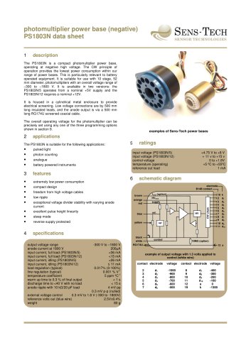
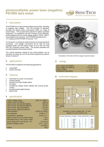
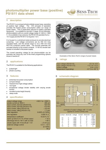
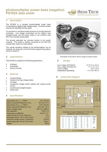
Examples of the Sens-Tech’s range of power bases
5
applications
The PS1818 is suitable for the following applications:
·
·
·
analogue
pulsed light
photon counting
input voltage (PS1818/5)
input voltage (PS1818/12)
control voltage
temperature (operating)
6
3
compact design
freedom from high voltage cables
extremely low ripple
exceptional voltage divider stability with varying anode
current
excellent pulse height linearity
sleep mode
schematic diagram
features
·
·
·
·
+4.75 V to +6.0 V
+12 V to +15 V
0 to +1.8 V
+ 5 °C to +55 °C
·
·
electrodes
B14B contacts
DC
HV
yellow
4
ref
13
14
11
3
10
4
9
5
6
k
d1
d2
d3
d4
d5
d6
d7
d8
7
red
active divider
2
ratings
a
specification
black
white
input power at Vmax = -1800 V
power conversion efficiency, PO / Pin
input power at Vmax = -1800 V
power conversion efficiency, PO / Pin
output voltage range
line regulation
temperature coefficient
warm up time to 0.3 % of final o/p
discharge time to <40 V with no load
maximum anode current, continuous
anode ripple with 100 kW //5 pF load
weight
+5 V, 65 mA
40 % for +5 V
+12 V, 20 mA
50 % for +12 V
-100 V to -1800 V
0.05 % /V
-1
<0.02 % °C
<2s
<2s
100 µA
100 µV
60 g
RG174U
example of output voltage with 1.100 V
applied to control (white) wire
contact electrode voltage contact electrode voltage
nc
nc
8
1
d6
d1
9
-400
-900
2
d4
d3
10
-600
-700
3
d2
d5
11
-800
-500
4
nc
d7
12
-300
5
k
d8
13
-1100
-100
6
d1
14
a
-900
floating
7
nc - no connection