عضویت
عضویت  ورود اعضا
 راهنمای خرید


PS18110 pages
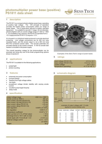
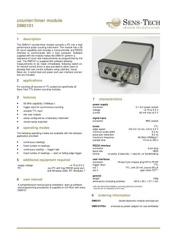
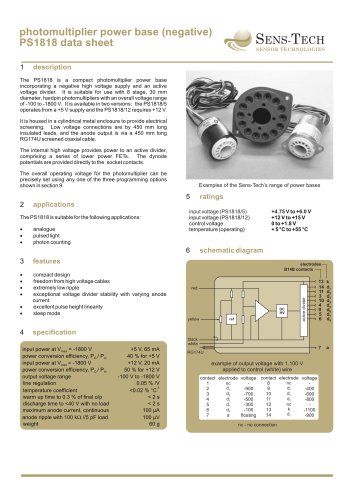
photomultiplier power base (positive)
PS1811 data sheet
1
SENS-TECH
SENSOR TECHNOLOGIES
description
The PS1811 is a compact photomultiplier power base, operating
at positive high voltage. The CW principle of operation
provides the lowest power consumption within our range of
power bases. This is particularly relevant to battery operated
equipment. It is suitable for use with 11 stage, 30 mm diameter,
photomultipliers with an overall voltage range of +300 to +1800
V. It is available in two versions: the PS1811/5 operates from a
+5 V supply and the PS1811/12 requires +12 V.
It is housed in a cylindrical metal enclosure to provide electrical
screening. Low voltage connections are by 450 mm long
insulated leads, and the anode output is via a 450 mm long
RG174U screened coaxial cable. The dynode potentials are
provided directly to the socket contacts. A 100 kW anode load
resistor is included in the power supply.
The overall operating voltage for the photomultiplier can be
precisely set using any one of the three programming options
shown in section 9.
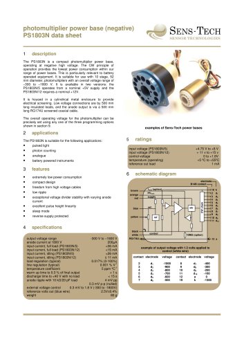
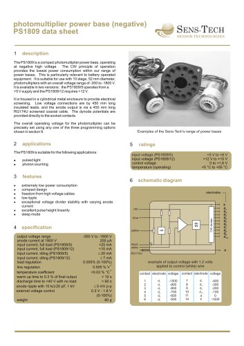
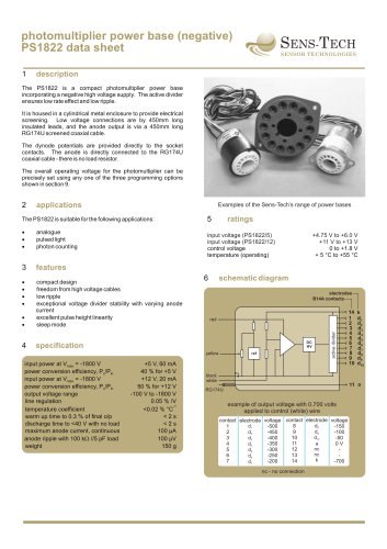
Examples of the Sens-Tech’s range of power bases
5
The PS1811 is suitable for the following applications:
·
·
pulsed light
photon counting
3
features
·
·
4
weight
+300 V to +1800 V
200 µA
<25 mA
<10 mA
£ 20 mA
£ 7 mA
0.005% (0-100%)
-1
0.005 % V
-1
<0.03 % °C
< 10 s
< 60 s
£ 5 mV p-p
0.3 V - 1.8 V
(0-100%)
80 g
+5 V to +8 V
+12 V to +15 V
0 to +1.6 V
+5 °C to +55 °C
schematic diagram
electrodes
red
DC
HV
yellow
specification
output voltage range
anode current at 1800 V
input current, full load (PS1811/5)
input current, full load (PS1811/12)
input current, idling (PS1811/5)
input current, idling (PS1811/12)
load regulation
line regulation
temperature coefficient
warm up time to 0.3 % of final output
discharge time to <40 V with no load
anode ripple with 10 kW/20 pF, 1 kV
external voltage control
input voltage (PS1811/5)
input voltage (PS1811/12)
control voltage
temperature (operating)
6
extremely low power consumption
compact design
freedom from high voltage cables
low ripple
exceptional voltage divider stability with varying anode
current
excellent pulse height linearity
sleep mode
·
·
·
·
·
ratings
applications
CW divider
2
ref
black
white
k
d1
d2
d3
d4
d5
d6
d7
d8
d9
d10
d11
100k
a
RG174U
example of output voltage with 1.3 volts
applied to control (white) wire
contact electrode voltage contact electrode voltage
d7
4
+800
d8
d1
9
+900
14
+200
d9
5
d2
+1000
12
+300
d10
8
d3
+1100
2
+400
6
d11
+1200
+500
11
d4
7
a
+1300
+600
3
d5
k
13
0
+700
10
d6