عضویت
عضویت  ورود اعضا
 راهنمای خرید


IO-CB series0 pages
Canbus-analogue-inst-e
28-01-2010
ISO9001 Certified
11:33
Pagina 1
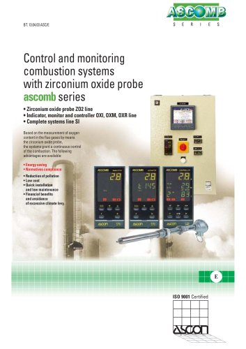
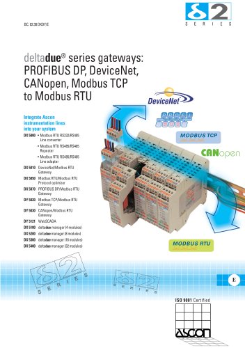
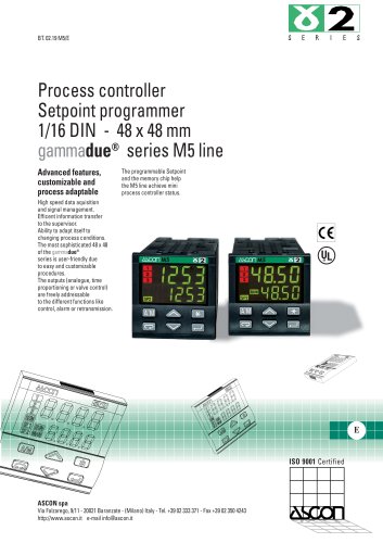
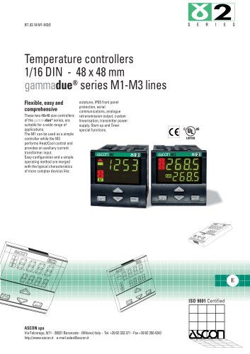
CANopen Analogue
I/O Modules
mod. IO-CB
M.I. IOA-CB-1/06.06
Cod. J30-658-1AIOA-CB E
Installation
Manual
ASCON spa
20021 Baranzate (Italy)
Fax +39 02 350 4243
www.ascon.it
sales@ascon.it
IO-CB/AI-02UI:
IO-CB/AI-04RT:
IO-CB/AI-08DP:
IO-CB/AI-08HL:
IO-CB/AI-08TC:
IO-CB/AO-08DP:
IO-CB/AO-08HL:
Contents
- General description
- Accessories
- Installation
- Electrical connections
- Electric safety
E
2 Isolated Analogue Inputs
4 Configurable Analogue Inputs
8 Voltage Analogue Inputs
8 Configurable Analogue Inputs
8 Thermocouple Analogue Inputs
8 ±10V Output Channels
8 High Level Analogue Inputs
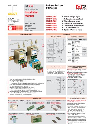
General description
Installation
Dimensions (mm)
Operating conditions
Environmental condition
7
6
70
64
Operating
conditions
110
8 LO
8 HI
5
9
46
76/152
45
1
66
10
2
40
Additional terminal block
Special
conditions
22
11
Forbidden
conditions
48
3
- Mount the module vertically
- In order to help the ventilation flow of
air, respect the distances between
modules and walls or other modules.
1
2
3
4
- Model identification label (on the back side of the module)
- DIN RAIL 35 x 7.5 (EN50022)
- 2 male 11 pole plugs, pitch 5.0mm
- 2 + 2 female, 11 pole, fast snap-ON connectors, pitch 5.0mm, with screw or
spring terminals to connect the power supply or the I/O (accessory)
5 - Two RJ45 plugs to connect the field bus
6 - CANopen cable with two RJ45 connectors (accessory)
7 - RJ45 plugs with internal termination circuitry (accessory)
8 - 2 rotary switches having 16 positions to set Node ID and Baud rate
9 - Removable and writable label to identify the connected I/O (TAG number)
10 - 4 status LEDs: identify the diagnostic and the module status
11 - Additional terminal block 2 x 11 poles (accessory)
min. 80
Mounting
position (mm)
Use forced
ventilation
Temperature
> 65°C
%Rh > 95% RH
Warm up
P Conducting
atmosphere
C Corrosive
atmosphere
Use filter
E Explosive
atmosphere
Mounting/removing the modules
on/from the DIN rail
Mounting position
4
%Rh Umidity 5...95% Rh
non condensing
T
21
Rail mounting
DIN 35 x 7.5
(EN 50022)
T
B Suggestion
Temperature
-10...+65°C
min. 60
64
1 Close the spring slide, then clip the upper
part of the module on the rail
2 Rotate the module downwards till to the click
3 Switch OFF the Power Supply
Lower the spring slide by inserting a flatblade screwdriver as indicated
4 Turn and lift the module upwards.
Mounting the module
2
1
CLICK
min. 100
Removing the module
3
4
Hot swapping the modules
Accessories
Power supply 45W - 2A/24 Vdc
11 poles connectors
Field bus cables with RJ45 connectors
AP-S2/AL-DR45-24
With screw terminals: AP-S2/SPINA-V11
With spring terminals: AP-S2/SPINA-M11
140 mm: AP-S2/LOCAL-BUS76
220 mm: AP-S2/LOCAL-BUS152
Power supply 120W - 5A/24Vdc
Additional terminal block
2 connectors with termination circuitry
AP-S2/AL-DR120-24
AP-S2/TB-211-1
AP-S2/TERM-CAN
Node ID and Baud rate of the new module
must already be correctly set.
The procedure to minimize the MODBUS
disconnection time follows:
1 Remove all the cabled connectors from
their plugs (item 4 in “General description” paragraph), do not extract the
MODBUS RJ45 connectors yet
2 Remove the module from the DIN rail
3 Mount the new and already configured
module on the DIN rail
4 Extract the left side RJ45 connector from
the module and insert it in the new module
5 Extract the right side RJ45 connector from
the module and insert it in the new module
6 Insert all the cabled connectors in the new
module.