عضویت
عضویت  ورود اعضا
 راهنمای خرید

45V, 10A Peak, Class C Power Amplifier0 pages

PA74/PA76 • PA74A/76A
PA74/76 • PA74A/76A
PA74, PA76, PA74A, PA76A
Power Dual Operational Amplifiers
FEATURES
•t LOW COST
•t WIDE COMMON MODE RANGE —
t
Includes negative supply
•t WIDE SUPPLY VOLTAGE RANGE
t
Single supply: 5V to 40V
t
Split supplies: ±2.5V to ±20V
•t HIGH EFFICIENCY — |Vs–2.2V| at 2.5A typ
•t HIGH OUTPUT CURRENT — 3A
•t LOW DISTORTION
8-PIN TO-3
PACKAGE STYLE CE
APPLICATIONS
R2
+28V 9K
R1
5K
•t HALF & FULL BRIDGE MOTOR DRIVERS
•t AUDIO POWER AMPLIFIER
t
STEREO — 30W RMS per channel
t
BRIDGE — 60W RMS per package
•t IDEAL FOR SINGLE SUPPLY SYSTEMS
t
5V — Peripherals, 12V — Automotive
t
28V — Avionic
R4
10K
R3
10K
+28V
_
_
M
A
+
COMMAND
INPUT
0/10V
B
1/2 PA74
R5
10K
+
1/2 PA74
R6
10K
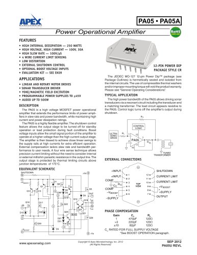
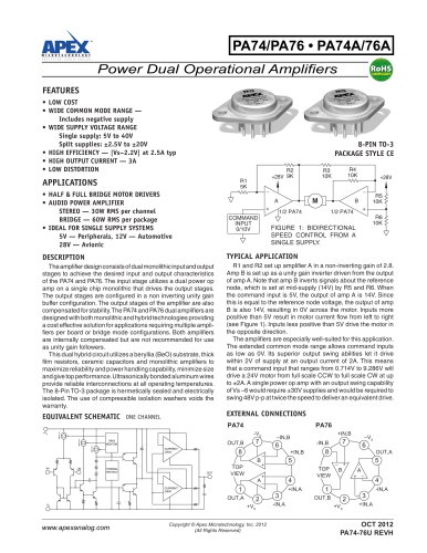
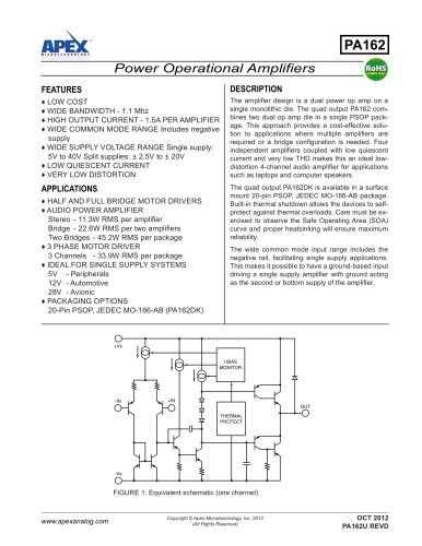
FIGURE 1: BIDIRECTIONAL
SPEED CONTROL FROM A
SINGLE SUPPLY.
DESCRIPTION
TYPICAL APPLICATION
The amplifier design consists of dual monolithic input and output
stages to achieve the desired input and output characteristics
of the PA74 and PA76. The input stage utilizes a dual power op
amp on a single chip monolithic that drives the output stages.
The output stages are configured in a non inverting unity gain
buffer configuration. The output stages of the amplifier are also
compensated for stability. The PA74 and PA76 dual amplifiers are
designed with both monolithic and hybrid technologies providing
a cost effective solution for applications requiring multiple amplifiers per board or bridge mode configurations. Both amplifiers
are internally compensated but are not recommended for use
as unity gain followers.
This dual hybrid circuit utilizes a beryllia (BeO) substrate, thick
film resistors, ceramic capacitors and monolithic amplifiers to
maximize reliability and power handling capability, minimize size
and give top performance. Ultrasonically bonded aluminum wires
provide reliable interconnections at all operating temperatures.
The 8-Pin TO-3 package is hermetically sealed and electrically
isolated. The use of compressible isolation washers voids the
warranty.
R1 and R2 set up amplifier A in a non-inverting gain of 2.8.
Amp B is set up as a unity gain inverter driven from the output
of amp A. Note that amp B inverts signals about the reference
node, which is set at mid-supply (14V) by R5 and R6. When
the command input is 5V, the output of amp A is 14V. Since
this is equal to the reference node voltage, the output of amp
B is also 14V, resulting in 0V across the motor. Inputs more
positive than 5V result in motor current flow from left to right
(see Figure 1). Inputs less positive than 5V drive the motor in
the opposite direction.
The amplifiers are especially well-suited for this application.
The extended common mode range allows command inputs
as low as 0V. Its superior output swing abilities let it drive
within 2V of supply at an output current of 2A. This means
that a command input that ranges from 0.714V to 9.286V will
drive a 24V motor from full scale CCW to full scale CW at up
to ±2A. A single power op amp with an output swing capability
of Vs –6 would require ±30V supplies and would be required to
swing 48V p-p at twice the speed to deliver an equivalent drive.
EQUIVALENT SCHEMATIC ONE CHANNEL
EXTERNAL CONNECTIONS
PA74
I BIAS
MONITOR
OUT,B
CURRENT
GAIN
-IN
PA76
-VS
+VS
+IN
THERMAL
PROTECT
8
OUT
CURRENT
GAIN
B
TOP
VIEW
A
1
OUT,A
-VS
www.apexanalog.com
PA74-76U
+VS
+IN,B
–IN,B
7
6
–
+
4
–
Copyright © Apex Microtechnology, Inc. 2012
(All Rights Reserved)
3
-IN,A
+IN,A
6
8
5
+
2
+IN,B
–VS
7
-IN,B
TOP
VIEW
–
B
+
+
1
OUT,B
+VS
2
OUT,A
5
A
–
3
4
-IN,A
+IN,A
OCT 2012
1
PA74-76U REVH