عضویت
عضویت  ورود اعضا
 راهنمای خرید


Grounding Connection System Catalog Section0 pages
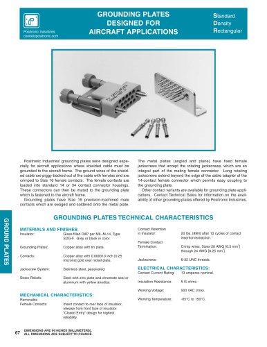
GROUNDING PLATES
DESIGNED FOR
AIRCRAFT APPLICATIONS
Positronic Industries
connectpositronic.com
Positronic Industries’ grounding plates were designed especially for aircraft applications where shielded cable must be
grounded to the aircraft frame. The ground wires of the shielded cable are piggy-backed out of the cable with ferrules and are
crimped to Size 16 female contacts. The female contacts are
loaded into standard 14 or 34 contact connector housings.
These connectors can then be mated to the grounding plate
which is fastened to the aircraft frame.
Grounding plates have Size 16 precision-machined male
contacts which are swaged and soldered onto the metal plate.
Standard
Density
Rectangular
The metal plates (angled and plane) have fixed female
jackscrews that accept the rotating jackscrews, which are an
integral part of the mating female connector. Long rotating
jackscrews extend beyond the edge of the cable adapter of the
14-contact female connector which permits easy coupling to
the grounding plate.
Other contact variants are available for grounding plate applications. Contact Technical Sales for information on the availability of other grounding plates offered by Positronic Industries.
GROUND PLATES
GROUNDING PLATES TECHNICAL CHARACTERISTICS
MATERIALS AND FINISHES:
Contact Retention
in Insulator:
20 lbs. (89N) after 10 cycles of contact
insertion/extraction.
Insulator:
Glass-filled DAP per MIL-M-14, Type
SDG-F. Grey or black in color.
Grounding Plates:
Copper alloy with tin plate.
Female Contact
Termination:
Contacts:
Copper alloy with 0.000010 inch [0.25
microns] gold over nickel plate.
Jackscrews:
Jackscrew System:
Stainless steel, passivated.
ELECTRICAL CHARACTERISTICS:
Strain Reliefs:
Steel with zinc plate and chromate seal or
aluminum with yellow anodize.
2
Crimp wires, Sizes 20 AWG [0.5 mm ]
2
through 24 AWG [0.25 mm ].
6-32 UNC threads.
Contact Current Rating:
13 amperes nominal.
Insulation Resistance:
5 G ohms.
Working Voltage:
500 VAC (rms).
Working Temperature:
-65°C to 150°C.
MECHANICAL CHARACTERISTICS:
Removable
Female Contacts:
67
Insert contact to rear face of insulator,
release from front face of insulator.
“Closed Entry” design for highest
reliability.
DIMENSIONS ARE IN INCHES [MILLIMETERS].
ALL DIMENSIONS ARE SUBJECT TO CHANGE.