عضویت
عضویت  ورود اعضا
 راهنمای خرید


LOADING

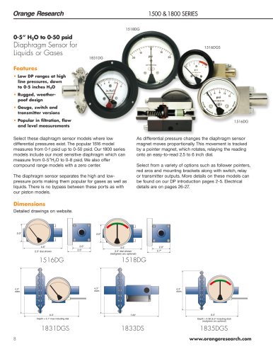
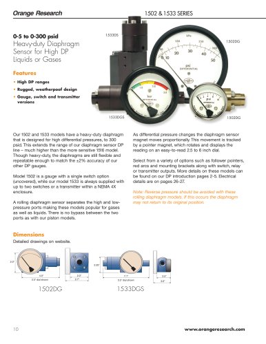
EXPLOSION-PROOF DP 0-5" H2O to 0-300 psid Piston or Diaphragm Sensors with Explosion-Proof Enclosures0 pages
نسخه متنی
"
"
| Orange Research | ||||||||||||||||||||||||||
| EXPLOSION-PROOF DP | ||||||||||||||||||||||||||
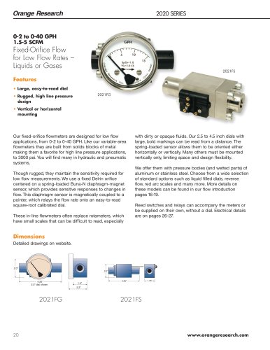
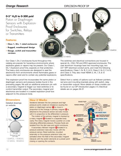
| 0-5" H2O to 0-300 psid Piston or Diaphragm Sensors with Explosion-Proof Enclosures for Switches, Relays or Transmitters Features • Class 1, Div. 1 rated enclosures ^ • Rugged, weatherpoof design • Gauge, switch and transmitter versions | ||||||||||||||||||||||||||
| 1514DGS | ||||||||||||||||||||||||||
| Our Class 1, Div. 2 enclosures found throughout this catalog are popular for hazardous environments where explosive gases or vapors may be present. Our Class 1, Div. 1 Explosion-proof line, expands on that protection. The heavy-duty enclosures are designed to seal the electronics from environments where flammable gases or vapors often exist and to contain any potential explosions. This explosion-proof line incorporates the same piston or diaphragm sensors and pressure bodies found in the preceding pages. We add an additional extension pin with a secondary magnet to trigger our reed switches or to control transmitter output. The secondary magnet and electronics are located in a sealed explosion-proof box adjacent to the pressure body. | ||||||||||||||||||||||||||
| The switches and electrical connections are housed in special UL, CSA, FM and ATEX approved enclosures. The cast aluminum housings have two mounting lugs, two 3/4" NPT electrical conduit ports, and meet the following specifications: Class 1, Gr. B, C, & D; Class 2, Gr. E, F, & G; and Class 3. They also meet NEMA 3, 4X, 7, 9, & 12 specifications. Select from a variety of options such as follower pointers, red arcs and mounting brackets along with switch, relay or transmitter outputs. More details on these models can be found on our DP introduction pages 2-5. Electrical details are on pages 26-27. | ||||||||||||||||||||||||||
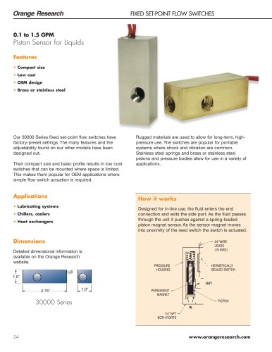
| How it Works Variations between the low pressure and high pressure ports create an imbalance causing the piston or diaphragm sensor 1 to move in proportion to the change. A primary magnet 2 is attached to the pressure sensor and also moves with it in proportion to the differential in pressure. The motion of the primary magnet is tracked by a rotary magnet 3 located in a separate body cavity. The rotary magnet moves a pointer on a dial indicating differential pressure. Process fluids are isolated from the dial case and switch enclosure. A secondary follower magnet 4 located in a pressure extension tube also moves with the pressure sensor. Reed switches, mounted externally on the pressure extension tube, are activated when the field of the secondary magnet interacts with the switch elements at a preset point closing or opening the contacts. | ||||||||||||||||||||||||||
| GAUGE FACE RANGE SPRING | ||||||||||||||||||||||||||
| Detailed drawings on website. | ||||||||||||||||||||||||||
| UPPER PRESSURE BODY | ||||||||||||||||||||||||||
| ODIAPHRAGM SENSING ELEMENT ©PRIMARY MAGNET ASSEMBLY | ||||||||||||||||||||||||||
| POINTER MAGNET & POINTER ASSY. HIGH PRESS. PORT | ||||||||||||||||||||||||||
| 11" max (13" 1 804) | ||||||||||||||||||||||||||
| 4.5" dial shown | ||||||||||||||||||||||||||
| PRESSURE EXTENSION TUBE | ||||||||||||||||||||||||||
| REED SWITCH | ||||||||||||||||||||||||||
| SECONDARY | ||||||||||||||||||||||||||
| SWITCH ADJUSTMENT | ||||||||||||||||||||||||||
| Enclosure 3.6" deep (3.9" 1804) 1204PGS, 1504DGS, 1514DGS, 1804DGS | ||||||||||||||||||||||||||
| SWITCH ENCLOSURE | ||||||||||||||||||||||||||
| TWO 3/4" CONDUIT PORTS | ||||||||||||||||||||||||||
| www.orangeresearch.com | ||||||||||||||||||||||||||
| 12 | ||||||||||||||||||||||||||