عضویت
عضویت  ورود اعضا
 راهنمای خرید


AX-100TFR/200TFR0 pages
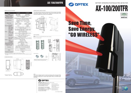
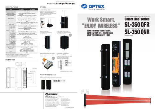
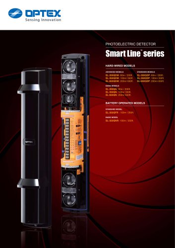
BATTERY OPERATED PHOTOELECTRIC DETECTOR
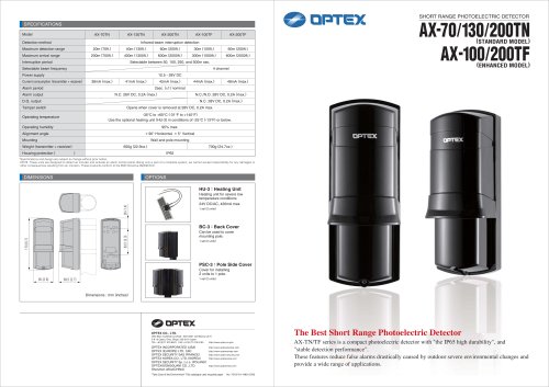
AX-100/200TFR
Current draw
*Battery life
Output
Transmitter
Receiver
Alarm output
Alarm period
D.Q. output
Low battery
output
Tamper output
for Front cover
Tamper output
for Back box
Alarm Indicator
(Receiver)
Indicator
Power
Transmitter)
Low battery
Operating temperature
Operating ambient humidity
Alignment angle
Mounting
Weight
International protection
Specifications and design are subject to change without prior notice.
* The value is based on the condition that it is used within the ambient temperature range of
20 to 25°C.
AX-100/200TFR
42.5(1.67)
42.5(1.67)
154(6.06)
Power Source
AX-200TFR
60m(200ft.)
30m (100ft.)
530m (1,740ft.)
265m (870ft.)
Infrared beam interruption detection
4 channel
Variable between 50, 100, 250, 500msec (4 steps)
3.6V 13.0Ah : LSH20 lithium batteries
manufactured by SAFT(not included)
Transmitter : 2 units Receiver : 2 units
810μA
620μA
T:300μA + R:320μA
T:490μA + R:320μA
(at 25°C,3.6VDC)
(at 25°C,3.6VDC)
3 years
5 years
5 years
Form C-Solid State Switch : 3.6 VDC, 0.01A
2 sec (± 1) nominal
Form A/B-Solid State Switch : 3.6 VDC, 0.01A
Form A/B-Solid State Switch : 3.6 VDC, 0.01A
(Transmitter & Receiver)
Form C : 3.6VDC, 0.01A
activates when cover removed. (Receiver only)
Form C : 3.6VDC, 0.01A
activates when either back box or chassis is
removed from the installment.
(1) Light on - IR Beam not received.
(2) Flickering Light - IR Beams not received sufficiently.
(3) Light off - IR Beams received.
Power ON : ON,
Power OFF : OFF
Voltage Reduction : flicker
-20°C – +60°C(-4°F – +140°F)
95%(Max.)
± 90° Horizontal, ± 5° Vertical
Indoor/Outdoor, Wall/Pole/Tower mounting
(Optional main unit mounting brackets are
required, when the units mount in the tower.)
1600g (56.5oz)
(Total weight of transmitter + receiver,excluding
accessories)
IP55
78(3.07)
AX-100TFR
Range
Maximum arrival distance
Detection method
Beam frequency selection
Interruption period
The following figure shows the dimensions of the wireless transmitter
installation space in the back box. Note that transmitters with
dimensions greater than those are not applicable.
78(3.07)
Model
SPACIOUS BACK BOX
154(6.06)
SPECIFICATIONS
BATTERY OPERATED PHOTOELECTRIC DETECTOR
66(2.60)
26.5(1.04)
26.5
(1.04)
OPTIONS
MP-4 : Main unit mounting bracket set (for tower mounting)
Main unit mounting bracket
Save Time,
Save Energy.
"GO WIRELESS"
Tamper Bushing
DIMENSIONS
Without the tamper busing, the LEDs are kept
ON,which consumes more battery power.
83.5(3.28)
217(8.5)
162.5(6.4)
88.1(3.47)
The pole size should be
43-48mm( 1.69"-1.98")
NOTE:
These units are designed to detect an intruder and activate an alarm control panel. Being
only a part of a complete system, we cannot accept responsibility for any damages or other
consequences resulting from an intrusion.These products conform to the EMC Directive
2004/108/EC.
OPTEX CO., LTD. (ISO 9001 Certified / ISO14001 Certified)
5-8-12 Ogoto, Otsu, Shiga, 520-0101 Japan
TEL +81(0)77 579 8670 FAX +81(0)77 579 8190
http://www.optex.co.jp/e/
OPTEX INCORPORATED (USA)
OPTEX (EUROPE) LTD. (UK)
http://www.optexamerica.com/
OPTEX SECURITY SAS (FRANCE)
OPTEX KOREA CO., LTD. (KOREA)
OPTEX SECURITY Sp. z o.o. (POLAND)
OPTEX (DONGGUAN) CO., LTD.
Shenzhen office (CHINA)
http://www.optex-security.com/
http://www.optex-europe.com/
(ISO9001 Certified)
http://www.optexkorea.com/
http://www.optex.com.pl/
http://www.optexchina.com/
No. 75116-00-15747-0904
The World Leader
in Sensors
for 30 years