عضویت
عضویت  ورود اعضا
 راهنمای خرید


M/261000/M0 pages
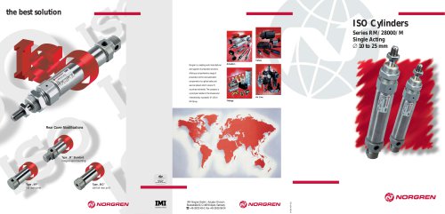
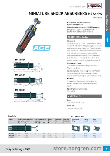
maximise output
minimise cost
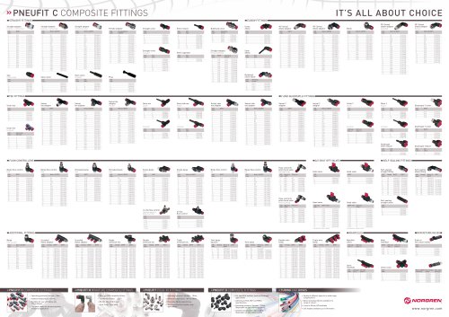
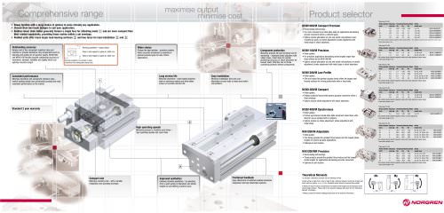
Comprehensive range
Product selector
**data sheet 2.3.001
• Seven families with a large choice of options to solve virtually any application.
• Choose from two basic designs to suit your application.
• Rodless linear slide tables generally feature a single face for attaching loads 1 and are more compact than
their rodded equivalents, providing linear motion within a set envelope.
• Rodded units offer much larger load bearing surfaces 2 and two faces for load installation 2 and 3 .
Outstanding accuracy
Reduce end of line component rejection rates and
machine or process downtime. Key components such as
bearings and guides are of superior quality. M/261000
and M/261100 families provide outstanding accuracy of
movement, strength, reliability and rigidity which can
optimise machine output.
Running parallelism - typical values:
Plane C with respect to plane A: 0,004 mm
Plane D with respect to plane B: 0,004 mm
Piston diameter Maximum Theoretical Moments (Nm)†
(mm)
load (kg) Mx
My
Mz
• Recirculating ball bearings.
• Our most compact linear slide table ideal for applications demanding
precise movement within a confined space.
• Options include alternative air port and switch rail positions; base
mounted air ports; no stroke adjustment; stroke adjustment with
metal stops or shock absorbers.
5 or 10
10 or 20
10 or 20
15 or 25
20 or 30
0,2
0,5
0,8
1,2
2,0
0,87
1,8
3,3
7,3
9,6
0,42
1,7
2,8
6,5
7,5
0,42
1,7
3,1
7,7
6,6
M/261006/IR5/IP/*
M/261008/MR6/IP/*
M/261010/MR6/IP/*
M/261012/MR6/IP/*
M/261016/MR6/IP/*
Part numbers denote standard magnetic models (except Ø6mm - non-magnetic only) with stroke adjustment (rubber stops).
* Insert stroke length in mm
**data sheet 2.3.003
Wider choice
Component protection
Piston diameter Maximum Theoretical Moments (Nm)†
(mm)
load (kg) Mx
My
Mz
• Roller guided.
• For precision applications demanding stroke lengths longer than
those offered by the M/261000/M.
• Options include alternative air port and switch rail positions; no stroke
adjustment; stroke adjustment with metal stops or shock absorbers.
Long service life
Easy installation
Minimise downtime and component rejection rates market leading design and construction provides the most
consistent performance on the market.
Minimise downtime - heat treated stainless
steel or aluminum bodies and slide tables
ensure an excellent service life.
Minimise installation time and cost alternative air port (side or base) and switch
rail positions.
15, 30 or 45
20, 30, 45 or 60
0,8
1,2
1,9
3,8
1,8
3,0
2,0
3,4
M/261110/MR6/IP/*
M/261112/MR6/IP/*
Part numbers denote standard magnetic models with stroke adjustment (rubber stops).
* Insert stroke length in mm
**data sheet 2.3.005
Piston diameter Maximum Theoretical Moments (Nm)†
(mm)
load (kg) Mx
My
Mz
8
10
15
20
M/261200/M Low Profile
Consistent performance
Stroke
length (mm)
10
12
M/261100/M Precision
Maximise product life and minimise cost of
ownership – standard stroke adjusters with
rubber stops, metal stops for greater
positioning accuracy or shock absorbers for
heavier loads. Effective end of stroke
cushioning protects internal components.
Choose the best solution - precision models
where accurate movement is essential or
general purpose types for less critical
applications.
Running parallelism: the variation in plane
movement of the sliding table during travel.
1
Stroke
length (mm)
6
8
10
12
16
M/261000/M Compact Precision
• Roller guided.
• Slim and robust this general purpose family offers the largest load
bearing surfaces for moving particularly wide or long loads.
1,5
2,0
4,0
8,0
1,3
2,1
4,5
1,3
0,45
0,79
1,6
3,6
0,45
0,88
1,7
3,4
Stroke
length (mm)
30, 45, or 60
30, 45 or 60
30, 45, 60, 80, or 100
30, 45, 60, 80 or 100
M/261208/MR/I/*
M/261210/MR/I/*
M/261215/MR/I/*
M/261220/MR/I/*
Part numbers denote standard magnetic models with stroke adjustment (rubber stops).
* Insert stroke length in mm
**data sheet 2.3.007
Piston diameter Maximum Theoretical Moments (Nm)†
(mm)
load (kg) Mx
My
Mz
M/261300/M Compact
• Roller guided.
• Rodless products that provide general purpose movement within a
fixed envelope.
• Options include stroke adjustment with shock absorbers.
10
16
0,8
2,0
1,8
3,6
1,3
1,9
1,3
1,9
Stroke
length (mm)
10, 20 or 30
10, 20 or 30
M/261310/MR6/IP/*
M/261316/MR6/IP/*
Part numbers denote standard magnetic models with stroke adjustment (rubber stops).
* Insert stroke length in mm
**data sheet 2.3.009
Standard 2 year warranty
M/261400/M Synchronous
Piston diameter Maximum Theoretical Moments (Nm)†
(mm)
load (kg) Mx
My
Mz
6
• Roller guided.
• Precise synchronous double slide table movement make these units
ideal for use as escapements or grippers.
• Options include no stroke adjustment; stroke adjustment with
metal stops.
2
Stroke
length (mm)
5 or 10
0,1
0,54
0,29
0,29
**data sheet 2.3.019
Piston diameter Maximum Theoretical Moments (Nm)†
(mm)
load (kg) Mx
My
Mz
M/61200/M Adjustable
• Slide guided.
• This family provides the greatest thrust values and the longest stroke
lengths for general purpose applications.
• Optional air port location.
Stroke
length (mm)
16
20
25
32
High operating speeds
Minimise process or machine cycle times –
high operating speeds and cycle rates.
25, 50, 75 or 100
25, 50, 75, 100 or 150
25, 50, 75, 100 or 150
25, 50, 75, 100 or 150
2
4
6
9
10,0
28,0
52,0
64,0
14,0
28,0
40,0
40,0
14,0
28,0
40,0
40,0
**data sheet 2.3.019
Piston diameter Maximum Theoretical Moments (Nm)†
(mm)
load (kg) Mx
My
Mz
16
20
25
32
• Recirculating ball bearings.
• These products provide the greatest thrust values and the longest
stroke lengths for applications demanding accurate movement.
• Optional air port location.
2
4
6
9
24,0
26,0
66,0
120,0
24,0
10,0
34,0
48,0
14,0
10,0
34,0
48,0
Stroke
length (mm)
25, 50, 75 or 100
25, 50, 75, 100 or 150
25, 50, 75, 100 or 150
25, 50, 75, 100 or 150
Part numbers denote standard magnetic models with stroke adjustment (rubber stops).
* Insert stroke length in mm
3
Improved aesthetics
Minimise machine cost - with a smaller
installation and operating envelope.
Enhance machine aesthetics - by selecting
from a wide variety of diameters and stroke
lengths to suit differing machine sizes.
Positional feedback
Easy attachment of switches enables seamless
integration into fully interlocked systems.
Theoretical Moments
To calculate a theoretical moment use the following formula Gravity acting on load (9,8) x mass of load W (kg) x distance between centre line of guide and
load’s centre of gravity, Lx, Ly, Lz (m). Calculated values should not exceed those stated.
† Maximum moment values correspond to the longest stroke length and will decrease as the
stroke length shortens. Please refer to the relevant catalogue data sheet for full ‘Theoretical
Moment’ information.
**Always consult the relevant catalogue data sheet for full technical information.
M/61216/M/*
M/61220/M/*
M/61225/M/*
M/61232/M/*
Part numbers denote standard magnetic models with stroke adjustment (rubber stops).
* Insert stroke length in mm
M/61200/MR Precision
Compact size
M/261406/MR1/I/*
Part numbers denote standard magnetic models, no stroke adjustment.
* Insert stroke length in mm
Mx
My
Mz
M/61216/MR/*
M/61220/MR/*
M/61225/MR/*
M/61232/MR/*