عضویت
عضویت  ورود اعضا
 راهنمای خرید


T series0 pages
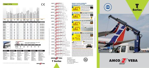
[ T Series: 2 -16 Tm
MOMENTO DJ SOLLEVAMENTO MAX. MOMENT D'ELEVATION MAX. MAX. HUBMOMENT MOMENTO DE ELEVACLON MAX. MOMENTO DE ELEVAQAO MAX. | SBRACCIOMAX.VERTICALE MAX LONGUEUR DU BRAS VERTICALE MAXVERTIKALE REICHWEITE ALCANCE MAX. VERTICAL ALCANCE MAX. VERTICAL | ANGOLO Dl ROTAZIONE ANGLE ROTATION SCHWENKBEREICH ANGULO DE ROTACLON ANGULO DE ROTACAO | VELOCITA Dl ROTAZIONE VITESSE DE ROTATION DREHGESCHWINDIGKEIT VELOCIDAD DE ROTACION VELOCIDADE DE ROTACAO | OO 35 O CQ< cc_i see go^|S = to°E<z LLIrr-< Z="<LLJ □ LLIO —;□ LU LU ^ = LU Q-OlS = Q_ | PRESSIONED'ESERCIZIO PRESSIONDE SERVICE BETRIEBSDRUCK PRESION DETRABAJO PRESSAODETRABALHO | PESO GRU SENZA STABILIZZATORI POIDS GRUE SANS STABILISATEURS KRANGEWICHT OHNE ABSTUTZUNGEN PESO DE LA GRUA SIN ESTABILIZADORES PESO DA GRUA SEM ESTABILIZADORES | PESO STABILIZZATORI POIDS DES STABILISATEURS GEWICHTDER ABSTUTZUNGEN PESO ESTABILIZADORES PESO DOS ESTABILIZADORES | CAPACITASERBATOIOOLIO CONTENANCE RESERVOIR HUILE OLBEHALTERHINHALT CAPACIDAD DEL TANQUE DE ACEITE CAPACIDADE DO TANQUE DE OLEO | PQRTATAALDISTRIBUTORE DEBIT D'HUILE HYDRAULIQUE AU DISTRIBUTEUR HYDRAULISCHE OLFORDERMENGE ZUM STEUERV CAUDAL DE ACEITE AL DISTRIBUDOR DESCARGA DE OLEO HIDRAULICO AO DISTRIBUID | ||
MODELS | MAX. LI FUNG MOMENT | MAX. VERTICAL REACH | SLEWING ANGLE | SLEWING SPEED | MAX. WORKING HEEL | WORKING PRESSURE | CRANE WEIGHT WITHOUT STABILIZERS | WEIGHT OF STABILIZERS | OIL TANK rADirnv CAPACITT | OIL FLOW TO THE CONTROL VALVE | DIMENSIONS |
I | Tm | m | O | s/180° | O | bar | kg | kg | Imin | mm BxhxS | |
805172s 805T/3S 805T/4S | 3.8 | 7.3 8.8 10.2 | 380 380 380 | 15 15 15 | 4 4 4 | 220 220 220 | 605 650 690 | 85 85 85 | 35 35 35 | 16 16 16 | 2080x1855x470 2080x1855x470 2085x1855x470 |
807IMT/2S 807NT/3S 807NT/4S | 6.7 | 8.0 9.5 11.0 | 387 387 387 | 15 15 15 | 4 4 4 | 260 260 260 | 780 840 900 | 100 100 100 | 35 35 35 | 18 18 18 | 2300x1995x550 2300x1995x550 2300x1995x550 |
809T/2S 809T/3S 809774s | 8.4 | 9.4 11.4 13.0 | 395 395 395 | 17 17 17 | 4 4 4 | 250 250 250 | 1000 1080 1145 | 190 190 190 | 60 60 60 | 20 20 20 | 2350x2290x590 2350x2290x590 2350x2290x590 |
811T/2S 811T/3S 811T/4S | 10.3 | 9.4 11.4 13.0 | 395 395 395 | 17 17 17 | 4 4 4 | 295 295 295 | 1000 1080 1145 | 190 190 190 | 60 60 60 | 20 20 20 | 2350x2290x590 2350x2290x590 2350x2290x590 |
816T/2S 816T/4S 816T/6S | 14.5 | 9.0 12.3 15.8 | 380 380 380 | 20 20 20 | 4 4 4 | 280 280 280 | 1360 1580 1740 | 200 200 200 | 100 100 100 | 30 30 30 | 2480x2380x770 2480x2380x770 2480x2380x770 |
818T/2S 818T/4S 818T/6S | 15.5 | 9.0 12.3 15.8 | 380 380 380 | 20 20 20 | 4 4 4 | 290 290 290 | 1380 1600 1760 | 200 200 200 | 100 100 100 | 30 30 30 | 2480x2380x770 2480x2380x770 2480x2380x770 |
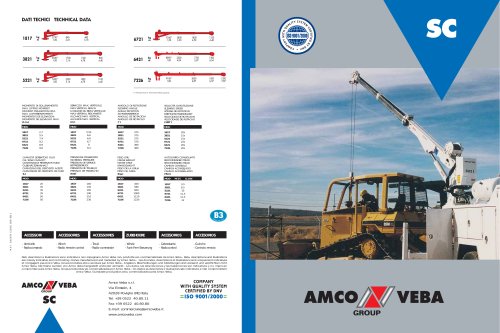
ACCESSOR!
Autocarro consigliato - Recommended track - Camion conseille
Camion aconsejado - Caminhao aconselhado
Mod. S05T 807NT 809T 811T 816T 818T
Passo*(mm) 3450 2700 3100
M.T.T.(ton) 5,0 6,5 12
G.V.W.(ton) 5,0 6,5 12
*) Wheelbase - Empattement - Passo
ACCESSORIES IACCESSOIRES IZUBEHORE
3100
12
12
3100
15
15
3100
15
15
ACCESORIOS IACCESORIOS
- Umitatore dl momenta
- Stabilizator! glrevdi
- Stabllbzatori allarjabili idrayllcamente
■ Stablllzzatorl extra estensibtli
(NO809T-811T)
■ Stablllzzatorl super extra estendiblll
(Solo816T-818T)
■ Attlvazlone element! supplemental!
■ Verricello
- Prolunghe meccaniche
- Posto dl manovra In alto
-Operator Full Protection
- Radlocomando
- Traverse supplemented
- Load limfo'ns device
-Turning stabilizers
- Outriggers with hydraulic extension
- Extra extensible stabilizers
(No SWT-811T)
■ Super-extra wide stabilizers
(Only816T-818T)
■ Supplementary elements activation
■Winch
- Mechanical booms
-Top seat
-OperatorFull Protection
- Radio-Remote control
-Additional cross beams
- Umiteurde moment
- Bequilles toumantes
- Bequilles avec ouverture hydraullque
- Stab. Extra-extensibles
(NO809T-811T)
■ Bequilles super extra larges
(Seulement 816T-818T)
■ Activation elements
supplementaires
■Treull
■ Rallonges mechaniques
■ Siege en haut
Operator Full Protection
■ Radiocommande
- Bequilles supplementaires
- Oberlastabschalter
-DrehbareAbstOtzbeine
- SeUch hydraulisch ausfahrbare
Abstutzstangen
- Extra-brelte Abstutzungen
(Nicht809T-811T)
- Super Extra-brelte Abstiitzungen
(Nur816T-818T)
- ZusatzfUnktionen
- Sellwlnde
- Mechanische VerlSngerungen
- Hoch Fuhrersitz
- Operator Full Protection
- Funkfemsteurung
- ZusatzabstOtzungen
-Umitadorde momenta
-Establllzadoresgiratorios
- Establllzsdores extraibles
hldraulicamente
- Estab. extra extensible:
(No 8WT-B11T)
■ Estab. super extra-largos
(S6k)811T-816T)
- Activaclon de elementos
suplementarbs
- Cabrestrantc
- Prolongs mecanlcas
-Puestodemandoarriba
- Operator Full Protection
- Radiomando
- Estabilizadores adicionales
-Varvula limltadora de momenta
decarga
- Estabilizadores glratortos
■ Estabilizadores estendldos
hldraulicamente
- Estabilizadores extra extens'rveis
(Nao809T-811T)
- Estabilizadores super-extra
extensfveis (Somente 816T-818T)
- Atjvacao de elementos suplementares
-Guinchodecabo
-Extensoes mecanlcas
- Posto de manobra no cimo
-OperatorFull Protection
-Comandopor Radio
- Estabilizadores adlcionais
1) La conformlta normatlva dsllappllcazlone tnoatrata deve aaaare valutata case per case. - Tna application ahown muat In evaluated on a casa-by-casa basis to establish compliance with standards.
AMCO/J/VEBA
805T/ZS
i
805T/3S
i
805T/4S
i
i
807NT/2S
i
i
807NT/3S
1
i
807NT/4S
1
i
809T/2S
1
i
809T/3S
1
i
809T/4S
1
i
811T/2S
1
1
811T/3S
1
811T/4S
1
1
816T/2S
3850* 2080 1190 830 585
1.0 1.85 3.20 4.57 6.03
\i 3760* 1930 11
II 1.0 1.95 3.!
3760* 1930 1110 765 585 425
1.0 1.95 3.30 4.67 6.03 7.50
kg
3630* 1770 1020 700 525 425 320
1.0 2.05 3.40 4.77 6.13 7.50 8.95
6730" 3300 1860 1290 930 690
1.0 2.04 3.60 5.15 6.80 8.45
3150 1770 1220 930 690 470
1.0 2.10 3.67 5.25 6.80 8.45 10.05
1.0 2.20 3.78 5.35 6.90 8.45 10.05
8400* 3300 1930 1350 1050 730
1.0 2.55 4.25 6.00 7.39 9.27
| 8300* 3240 1860 1275 970 750
1.0 2.55 4.25 6.00 7.75 9.27
| 8200* 3200 1810 1215 910 725
1.0 2.55 4.25 6.00 7.75 9.55
110350* 4060 2400 1670 1300 970
1.0 2.55 4.25 6.00 7.39 9.27
10200* 4000 2320 1600 1225 970
1.0 2.55 4.25 6.00 7.75 9.27
11 10100* 3950 22
II 1.0 2.55 4.
10100* 3950 2275 1550 1170 940
1.0 2.55 4.25 6.00 7.75 9.55
14500* 6160 3640 2570 1750 1410 1030
1.0 2.36 3.96 5.56 7.36 9.02 10.90
818T/4S
818T/6S
15100 * 6100 3600 2510 1885 1520 1115 945 745
1.0 2.48 4.08 5.68 7.36 9.02 10.80 12.60 14.70
14800' 5880 3410 2340 1730 1360 1115 945 745
1.0 2.52 4.15 5.75 7.40 9.05 10.80 12.60 14.70
) Portata teorica - Theoretical lifting capacity
Sistemi di controllo stabilita (CE)
Stability control systems (CE)
M System BOST | ||
■■aaaaMT II ioo%|,|,i ( b _ | ]fi 100% (_} f 100% | L'M System integrate nel Umitatore di momenta ^^^^^^ controlla la posizlone degli stabilizzatori. ■ Solo quando tutte le aste sono completamente ■ aperte e tutti gli stabilizzatori sono appoggiati a ■ terra la gru puo operare e sollevare il carico. ^h^LVLlftV |
J ,1,1100% | The M System Integrated in the load limiting device Control display checks the stabilizers' positions. Only when all beams are fully open and all stabilizers are on the ground the crane can operate and lift loads. | |
ML System RRS 905T - 907NT
L'ML System integrate nel limitatore di momento
controlla la posizlone degli stabilizzatori.
Solo quando tutte le aste sono completamente
aperte e tutti gli stabilizzatori sono appoggiati a
terra la gru puo operare e sollevare il carico.
The ML System integrated in the load limiting
device checks the stabilizers'positions. Only when
all beams are fully open and all stabilizers are on
(fte ground the crane can operate and lift loads.
Control display
9000
XL System 807NT - 809T - 811T - 816T - 818T
L'XL System integrato nel limitatore di momento
controlla la posizione degli stabilizzatori. Solo quando
tutte le aste sono completamente aperte e tutti gli
stabilizzatori sono appoggiati a terra la gru pud
operare e sollevare II carico. II display dell'EBB
consente all'utilizzatore di vedere la posizione degli
stabilizzatori.
The XL System integrated in the load limiting device
stabilizers' positions. Only when all beams are
and all stabilizers are on the ground the crane can opt
loads. The EBB display allows the user to see the stabilizers'
Optional RCS
II Rotation Control Sensor controlla costantemente la posizione
della rotazione della gru e limita la capacita di carico a seconda
della posizione delle aste e dei piedi degli stabilizzatori.
The Rotation Control Sensor constantly checks the slewing
position of the crane and limits the lifting capacity depending
on the beams'and the stabilizers'positions.
checks the
fully open
and lift
2XL System RRS
809T - B11T - 816T - 818T
100%
4r
15% 70% 100%
»l »l »l
0% 50% 100%
V II PES (Proportional Encoder Sensor)
^BMU riconosce 3 posizioni delle aste degli stabi-
QEO I Nzzatori: aperte, semiaperte e comple-
\ tamente chiuse.
The PES (Proportional Encoder Sensor) recognizes 3
positions of the stabilizer's beams: fully open, half
extended, fully closed.
U EBB controlla la posizione degli stabilizzatori. e i
divide I'area del camion in 4 settori di rotazione: sopra I
la cabina, lato destro, lato sinistra e retro. A seconda I
della posizione delle aste e dei piedi degli stabilizzatori, f
la capacita di carico della gru cambia secondo le I
impostazioni fatte daH'installatore. Questo permette I
all'operatore di usare la gru senza problemi di stabilita
anche quando un'asta e parzialmente o completamente retratta.
The EBB checks the positions of the stabilizers and divides the
working area into 4 slewing sectors: over the cabin, right side, left
side and the rear of die vehicle. Depending on the position of the
beams and the stabilizers, the crane's lifting capacity changes according
to tile settings made by the installer. This allows the operator to use
the crane even with a beam partially or fully retracted without having
stability problems.
II radiocomando CAN-BUS permette all'operatore di conoscere
la posizione degli stabilizzatori e le condizioni di carico della gru.
The CAN-BUS radio-control allows the operator to know the positions
of the stabilizers and the loading conditions of the crane.
D^C L" RCS (Rotation Control Sensor) riconosce
twO 4 settori di rotazione: sopra la cabina, lato
destro, lato sinistra e retro del veicolo.
The RCS (Rotation Control Sensor) recognizes 4 slewing
sectors: over the cabin, right side, left side, to the rear
of the vehicle. _
mm
No con stabilizzatori allargabili manualmente standard. Unavailable on cranes with manually opening stabilizers.
- Dati. descrizioni e illustraziorii sono relat'wi solo ed unicamente ai modelli commBrcializzati alia data dl stampa di questo depliant. Succossivamente alia data dl stampa quests
informazioni sono meramente Indicative e non impegnano Amco Veba. Eventuali variazioni sono a discre?ione di Amco Veba e sono sempre nel rispetto delle normative di sicurezza
pertinenti ed applicabili. Per ottenere dati, descrizioni ed illustrazioni aggiornati, fare riferimento al costruttore a al rivenditore. Gru prodotte e/o commercializzate da Amco Veba.
- Data, descriptions and Illustrations pertain only and uniquely to models sold at the time of printing of Oils brochure. After the date of printing, this Information Is purely Indicative
and not binding upon Amco Veba. Future modifications are solely at the discretion of Amco Veba and are always in compliance with applicable and pertinent safety standards. To
obtain updated data, descriptions and illustrations, contact the manufacturer or your reseller. Cranes manufactured and/or marketed tiy Amco Veba. - Les donnEles, les ctescriptions
el les illustrations se rapportenl seulement et exclusivement aux modeles commercialises a la date d'impression de ce depliant Apres la date depression, ces informations son)
simplement indicatives et n'mgagertt pas Amco Veba. UeVentuelles modifications sont a la discretion d'Amco Vebaet toujours dans I'observance des normes desficuritfi pertinentes
et applicable. Pour ubtenir les donni.es, les descriptions et les illustrations actualists, s'adresser au fabricant ou au revendeur. Grues produites et/ou vendues par Amco Veba. -
Daten, Beschreibungen und Abbildungen beziehen sich ausschlieBlich auf die zum Zeitpunkt des Drucks dieser Broschure vertriebenen Modelle. Nach diesem Datum verstehen
m Fall ftlr Amco Veba verbindlich. Amco Veba behSIt sich vor, nach eigenem Ermessen und in jedem Fall unter
BerDcksichtigung der zugehtJriger und geltenden Sicherheitsvorsctiriften Anderungen vorzunehmen. Bitte wenden Sie sich fOr aktuelle Daten, Beschreibungen und Abbildungen
an den Hersteller eder Handler. Die KrSne werden von Amco Veba hergestellt und/oder vermarrt. - Les dates, descr'pcionss e ilustrac'oies corresponden dnicamente a los
modElas comercializados tiasta la lecba de irnpresion de este folleto, DespuSs de la fecha de impresifln estos dates sen solo coma referenda y no comprometen a Amw Veba,
Las posibles variaciones son a discrecifin de Amco Veba y son confornes a las normas de seguridad pertinentes y aplicables. Para obtener datos, descripciones e ilLstraciones
actual'eadas, dingirse al fahricantE o al disiibuidor, Guas pnxlucidas y/o comercfalizadas por Amen Veca. - Ds dados, descricfi-s e ilustragOes referem-ss dnica e exclusivamentB
aos modelos comercializados i data da imprassSo deste folheto. Apfls a data da imprassSo, estas informacOss sao meramsnts indicativas pelas quafs a Amco Veba nao se
responsabiliza. Eventuais alteracdes Ream ao crite'rio da Amco Veba e estao sempre em conformidade com as normas de seguranca pertinentes e aplicSreis. Para obter dados,
descrigOes e ilustragOes adiializados, contacte o fabricante ou reveidedor. Guindaste produzidos e/ou comercializados pela Amco Veba
AMCO/S^YEBA
GROUP
T Series
Amco Veba s.r.l.
Via Einstein, 4
42028 Poviglio (RE) Italy
Tel. +39 0522 40.80.11
Fax+39 0522 40.80.80
E-mail: commerciale@amcoveba.it
www.amcoveba.com
i!
II
p
II
1!
II
If
AMCO ^ VEBA
GROUP
"