عضویت
عضویت  ورود اعضا
 راهنمای خرید


Inverter Communication Accessories KB DLM0 pages

Model DLM-1000, Part No. 14145
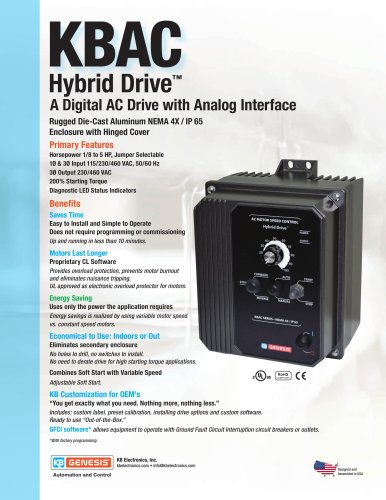
nnUploads, Downloads andStores Programs to and from theKBE2, KBN2, KBV2, KBVF* and KBAC*Adjustable Frequency Drives and Drive-Linkٙ
nnDownLoad Module(Part No. 14145)
nnSTANDARD FEATURES DESCRIPTION
The DownLoad Moduleٙ (DLM) is designed to store and transfer upto 10 programs for the KBE2, KBN2, KBV2, KBVF* and KBAC* AdjustableFrequency Drives. A program consists of an entire set of drive functions.
The DLM can be used to program individual or multiple drives and becauseit is powered from the PC or the drive, it does not require a separate powersupply or battery. Optional Drive-Link Software allows the DLM to beprogrammed from a PC running Windowsٮ 95/98/2000/ME/XP/NT. TheDLM can be used as a handheld device or permanently mounted.The DLM is easy to operate. The DriveӔ Switch sets the drive whichwill be connected to the DLM. The Program No.Ӕ Switch selects up to 10
program storage locations. The ConnectionӔ Switch sets the DLM modeof operation. Push buttons are used to initiate data transfer.The DLM has three modes of operation. In PC to DLM to DriveModeӔ, the DLM is used as an interface between Drive-Link and thedrive. In ٓPC to DLM Mode, the DLM is programmed from Drive-Linkԙ.In DLM to Drive ModeӔ, the DLM is programmed from a drive and the pro-gram can be transferred to other drives. In addition, a program stored in
the DLM can be transferred to the Drive-Link program.LED Status Indicators provide cable connection status (power) anddata transfer status (transmit, receive). Connection from the DLM to thedrive is made with the optional DLM to drive cable. Connection from the
DLM to the PC is made with a standard DB-9 Serial cable. The DLM is factory set for optimum communication performance forall of the drives. The Setup Jumpers are easily accessible by removing theslide cover. They allow communication settings (baud rate, data bits, stopbits, parity), default or manual jumper settings, and power saving mode(enables or disables the program LEDs). To tailor the DLM for a specific
communication requirement, set Jumper J10 to the ٓMAN position andset the other jumpers to the desired setting. >
LED STATUS INDICATORS
ԕ Program Drive to DLM Provides status of data transfer from thedrive to the DLM.֕ Program DLM to Drive Provides status of data transfer from theDLM to the drive.֕ PC (PWR/T/R) Provides status of power, signal transmit and receivefrom the DLM to the PC.֕ Drive (PWR/T/R) Provides status of power, signal transmit andreceive from the DLM to the Drive.
֕10 Program Storage CapacityNo Separate Power Supply or Battery RequiredՕCan be Handheld or Permanently MountedNon-Volatile MemoryՕSimple to OperateConfigurable Communication SettingsՕCan be Used Independently or with a PC >
SWITCH SELECTABLE FEATURES
Drive Switch Ֆ Sets Communication with the DLM and KBE2, KBN2,KBV2, KBVF* or KBAC* Adjustable Frequency Drives. Connection Switch Ֆ Selects the type of data transfer. Program No. Switch Ֆ Selects up to 10 different programs. >
nnCOMMUNICATION AND SETUP JUMPERS
J1: PC to DLM Baud Rate (4800, 9600 , 19200, 38400)Օ J2: PC to DLM Data Bits (7, 8 ) J3: PC to DLM Parity ( Even , Odd, None)Օ J4: PC to DLM Stop Bits ( 1 , 2) J5: Drive to DLM Baud Rate (4800, 9600 , 19200, 38400)Օ >
nnOPTIONAL ACCESSORIES
J6: Drive to DLM Data Bits (7, 8 ) ՕDLM to KBE2 Communication Cable (Part No. 14147)DLM to KBN2 Communication Cable (Part No. 14152)ՕDLM to KBV2 Communication Cable (Part No. 14155)DLM to KBVF* and KBAC* Communication Cable (Part No. 14148)ՕDrive-Link Software with PC to DLM Serial Port CommunicationCable (Part No. 14165)Drive-Link Software with PC to DLM USB Port CommunicationCable (Part No. 14166) J7: Drive to DLM Parity ( Even , Odd, None)Օ J8: Drive to DLM Stop Bits ( 1 , 2) J9: Enables or Disables the Programming LEDs ( On , Off)Օ J10: Default or Manual Setup for Selected Drive ( Default , Manual) >
(Bold Print Indicates Factory Setting) * Version 2GӔ and above, use KBV2 Position