عضویت
عضویت  ورود اعضا
 راهنمای خرید


LOADING

Motion Control 1CE200 pages
نسخه متنی
"
"
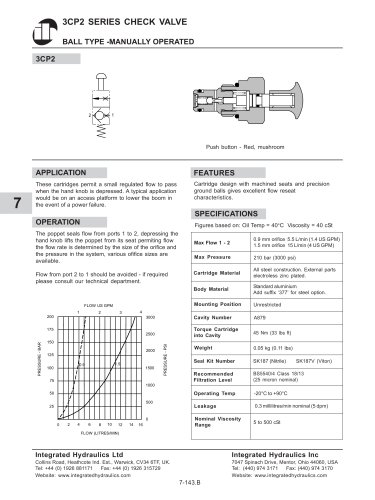
| 1CE SERIES OVERCENTRE VALVE PILOT ASSISTED RELIEF WITH CHECK | |||||||||||||||||||||||||||||||||||||
| APPLICATION | PILOT RATIOS | ||||||||||||||||||||||||||||||||||||
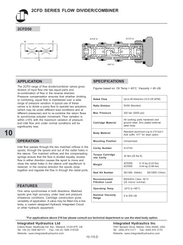
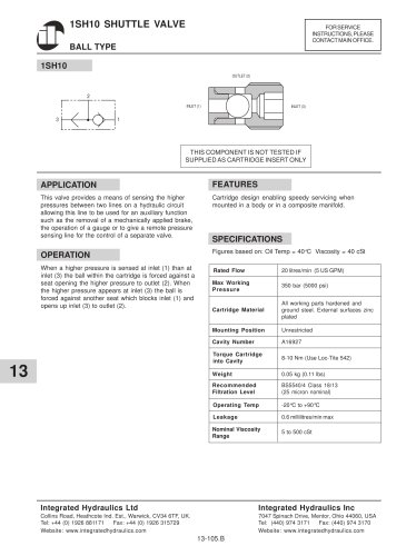
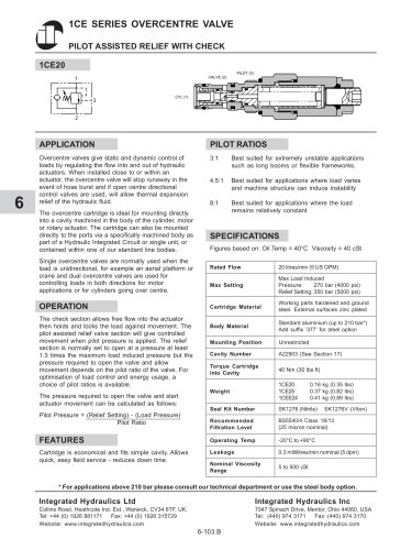
| Overcentre valves give static and dynamic control of loads by regulating the flow into and out of hydraulic actuators. When installed close to or within an actuator, the overcentre valve will stop runaway in the event of hose burst and if open centre directional control valves are used, will allow thermal expansion relief of the hydraulic fluid. The overcentre cartridge is ideal for mounting directly into a cavity machined in the body of the cylinder, motor or rotary actuator. The cartridge can also be mounted directly to the ports via a specifically machined body as part of a Hydraulic Integrated Circuit or single unit, or contained within one of our standard line bodies. Single overcentre valves are normally used when the load is unidirectional, for example an aerial platform or crane and dual overcentre valves are used for controlling loads in both directions for motor applications or for cylinders going over centre. OPERATION The check section allows free flow into the actuator then holds and locks the load against movement. The pilot assisted relief valve section will give controlled movement when pilot pressure is applied. The relief section is normally set to open at a pressure at least 1.3 times the maximum load induced pressure but the pressure required to open the valve and allow movement depends on the pilot ratio of the valve. For optimisation of load control and energy usage, a choice of pilot ratios is available. The pressure required to open the valve and start actuator movement can be calculated as follows: Pilot Pressure = (Relief Setting) - (Load Pressure) Pilot Ratio FEATURES Cartridge is economical and fits simple cavity. Allows quick, easy field service - reduces down time. | |||||||||||||||||||||||||||||||||||||
| 3:1 Best suited for extremely unstable applications such as long booms or flexible frameworks. 4.5:1 Best suited for applications where load varies and machine structure can induce instability 8:1 Best suited for applications where the load remains relatively constant | |||||||||||||||||||||||||||||||||||||
| 6 | |||||||||||||||||||||||||||||||||||||
| SPECIFICATIONS Figures based on: Oil Temp = 40°C Viscosity = 40 cSt | |||||||||||||||||||||||||||||||||||||
| |||||||||||||||||||||||||||||||||||||
| * For applications above 210 bar please consult our technical department or use the steel body option. | |||||||||||||||||||||||||||||||||||||
| Integrated Hydraulics Ltd Collins Road, Heathcote Ind. Est., Warwick, CV34 6TF, UK. Tel: +44 (0) 1926 881171 Fax: +44 (0) 1926 315729 Website: www.integratedhydraulics.com | Integrated Hydraulics Inc 7047 Spinach Drive, Mentor, Ohio 44060, USA Tel: (440) 974 3171 Fax: (440) 974 3170 Website: www.integratedhydraulics.com | ||||||||||||||||||||||||||||||||||||
| 6-103.B | |||||||||||||||||||||||||||||||||||||