عضویت
عضویت  ورود اعضا
 راهنمای خرید


Clapet Check valve , metal seal N60 pages
Boiler room components
0314EN May 2015
Clapet check valve, metal seal
N6
ISO
9001
0006/7
ISO
14001
0032A/3
OHSAS
18001
0064L/1
Technical data
• ompatible fluids: water for heating systems, domestic hot water, water
C
containing glycol (max. 30 % glycol)
• Connections: female threaded ISO 228
• Temperature range: 5÷95 °C (110 °C for occasional peaks)
• Max. working pressure: 16 bar
• Opening pressure: 0,05 bar
Materials
• Valve body: brass UNI EN 12165 - CW617N (3/8”÷1”)
brass UNI EN 1982 - CB753S (1 1/4”÷3”)
• Cap: brass UNI EN 12165 CW617N
O-ring : NBR
• Shutter: brass UNI EN 12165 CW617N
N6
Losses of pressure
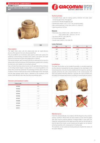
The clapet check valves with N6 metal seal are single-direction devices which
percent the return of pressurised fluid. They are suitable for use in domestic
water systems, raised water systems, fire protection, central heating and boiler
room systems, solar plants, and water systems for industrial and agricultural
applications in general. The internal hydraulic seal is ensured by the forces
exercised by the mass of a tilting shutter and by the pressure of the liquid
above a gasket which activates the seal, even when subject to minimal back
pressure.
Due to the fact that these valves function via the gravitational force that acts
on the tilting shutter (clapet or swing), there is no universal guideline as to
where these should be positioned. The advantage of these valves is the low
incidence of losses of pressure due to the rounded shape of the valve body
and the large passage section which is obtained via the oscillation of the
shutter; these elements also mean that they are extremely quiet.
Kv
Size
Kv
3/8”
Description
Size
2,9
1 1/2”
26,7
1/2”
6,5
2”
42,8
3/4”
10,5
2 1/2”
61,4
1”
17,8
3”
103
1 1/4”
19,8
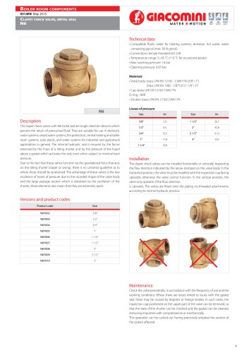
Installation
The clapet check valves can be installed horizontally or vertically, respecting
the flow direction indicated by the arrow stamped on the valve body. In the
horizontal position, the valve must be installed with the inspection cap facing
upwards; otherwise the valve cannot function. In the vertical position, the
valve only operates if the flow direction
is upwards. The valves are fitted onto the piping via threaded attachments,
according to normal hydraulic practice.
Versions and product codes
Product code
Size
N6Y002
3/8”
N6Y003
1/2”
N6Y004
3/4”
N6Y005
1”
N6Y006
1 1/4”
N6Y007
1 1/2”
N6Y008
2”
N6Y009
2 1/2”
N6Y010
3”
Maintenance
Check the valve periodically, in accordance with the frequency of use and the
working conditions. Where there are losses linked to issues with the gasket
seal, these may be caused by deposits or foreign bodies. In such cases, the
inspection cap positioned on the upper part of the valve can be removed, so
that the state of the shutter can be checked and the gasket can be cleaned,
removing impurities with compressed air or mechanically.
This operation can be carried out having previously emptied the section of
the system affected.
1
"