عضویت
عضویت  ورود اعضا
 راهنمای خرید


Common mode impedance FIN9000 pages
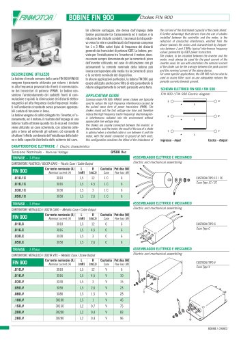
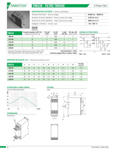
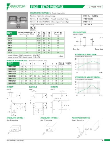
BOBINE FIN 900
Chokes FIN 900
Un ulteriore vantaggio, che deriva dall’impiego delle
bobine posizionate tra l’azionamento ed il motore, è la
riduzione dei disturbi condotti, trasmessi dal dispositivo verso la rete e caratterizzati da frequenze comprese
tra 1 e 3 MHz: valori tipici di frequenza dei disturbi
generati dai transistori di potenza IGBT. Le bobine, previste per l’installazione tra l’inverter ed il motore, devono essere sempre dimensionate per la corrente di picco
dell’inverter utilizzato; nel caso di utilizzazione con gli
azionamenti la corrente nominale della bobina può
invece corrispondere alla media tra la corrente di picco
e la corrente nominale del dispositivo.
In alcune applicazioni particolari, la bobina FIN 900 può
essere utilizzata anche come filtro di rete consentendo di
ridurre adeguatamente le correnti parassite verso terra.
APPLICATION GUIDE
DESCRIZIONE UTILIZZO
Le bobine di modo comune della serie FIN 900/FIN930
vengono tipicamente utilizzate per ridurre i disturbi
in alta frequenza provocati dai fronti di commutazione dei transistori di potenza (PWM). Le bobine consentono l’arrotondamento dei suddetti fronti di commutazione e quindi la diminuzione dei disturbi elettromagnetici ad alta frequenza (radio frequenza) irradiati nell’ambiente circostante senza provocare apprezzabili cadute di tensione in linea.
Le bobine vengono di solito collegate tra l’inverter, o l’azionamento, ed il motore; il risultato dell’impiego di una
bobina risulta ottimale quando tra di essa ed il motore
viene utilizzato un cavo schermato, con schermo collegato a terra ad entrambi gli estremi; ciò consente di
sfruttare l’effetto combinato dell’induttanza della bobina e della capacità distribuita dello schermo del cavo.
the coil and of the distributed capacity of the cable shield.
A further advantage that derives from the use of chokes
installed between the controller and the motor, is the
reduction of conducted interference, emitted from the
device towards the mains and characterised by frequencies between 1 and 3 MHz: typical interference frequency
values generated by IGBT power transistors.
The chokes, to be installed between the inverter and the
motor, must always be sized for the peak current of the
inverter used; for use with controllers the nominal current
of the choke can be the average between the peak current
and the nominal current of the above device.
For some specific applications, the FIN 900 coil can also be
used as mains filter; such an use adequately reduces the
parasite currents towards ground.
FIN 900 / FIN 930 Electric diagram
Common node F IN 900/ FIN930 series chokes are typically
used to reduce the high frequency interferences caused by
the pulsed wave form of power transistors (PWM). The
chokes round out the fast voltage rise time and therefore
reduce the high frequency (radio frequency) electromagnetic interferences radiated into the environment without
appreciable line voltage drop.
The chokes are usually connected between the inverter, or
the controller, and the motor; the result of the use of a choke
is optimal when a shielded cable is run between it and the
motor, with the shield connected to ground at both ends;
this configuration combines the effect of the inductance of
SCHEMA ELETTRICO FIN 900 / FIN 930
3'
3
L
2'
2
L
1'
1
L
Ingresso - Input
Uscita - Output
CARATTERISTICHE ELETTRICHE / Electric characteristics
Tensione Nominale - Nominal Voltage
0/500 VAC
ASSEMBLAGGIO ELETTRICO E MECCANICO
TRIFASE – 3-Phase
Electric and mechanical assembling
CONTENITORE PLASTICO / USCITA CAVO – Plastic Case / Cable Output
FIN 900
Corrente nominale (A)
3X10
L
(mH)
1,5
R
(mΩ)
12
.010.1C
.016.1C
3X16
1,5
.030.1C
3X30
1,5
.050.1C
3X50
1,5
Nominal current (A)
Custodia Pot diss (W)
Case
Pow loss (W)
1C
6
4,5
1C
6
3
1C
6
2,6
1C
6
CUSTODIA TIPO 1C / 2C
Case Type 1C / 2C
ASSEMBLAGGIO ELETTRICO E MECCANICO
TRIFASE – 3-Phase
Electric and mechanical assembling
CONTENITORE METALLICO / USCITA CAVO – Metallic Case / Cable Output
FIN 900
Corrente nominale (A)
3X10
L
(mH)
1,5
R
(mΩ)
12
.010.C
.016.C
3X16
1,5
4,5
.030.C
3X30
1,5
3
C
6
.050.C
3X50
1,5
2,6
C
6
Nominal current (A)
Custodia Pot diss (W)
Case
Pow loss (W)
C
6
C
6
CUSTODIA TIPO C
Case Type C
ASSEMBLAGGIO ELETTRICO E MECCANICO
TRIFASE – 3-Phase
Electric and mechanical assembling
CONTENITORE METALLICO / USCITA VITE – Metallic Case / Screw Output
FIN 900
Corrente nominale (A)
3X10
L
(mH)
1,5
R
(mΩ)
12
.010.V
.016.V
3X16
1,5
4,5
.030.V
3X30
1,5
3
V
15
.050.V
3X50
1,5
2,6
V
23
.080.V
3X80
1,5
1,5
V
28
.100.V
3X100
1,5
1
V
45
.150.V
3X150
1,2
0,7
V
75
.200.V
3X200
1,2
0,4
V
83
.280.V
3X280
1,2
0,4
V
96
Nominal current (A)
Custodia Pot diss (W)
Case
Pow loss (W)
V
6
V
CUSTODIA TIPO V
Case Type V
10
BOBINE / CHOKES