عضویت
عضویت  ورود اعضا
 راهنمای خرید


EDFHG-04/06 (Proportional directional and flow control valves)0 pages

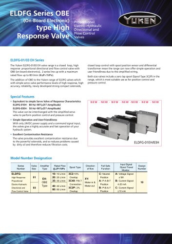
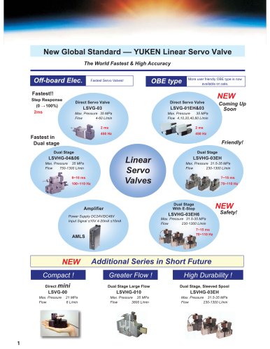
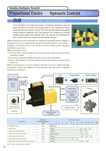
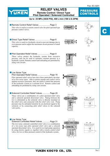
Proportional ElectroHydraulic Directional and
Flow Control Valves
25 MPa
Max. Operating Pressure
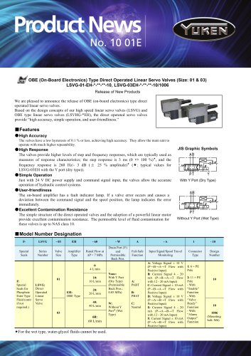
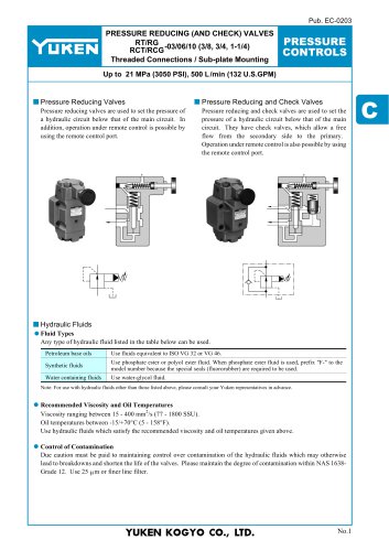
Proportional Electro-Hydraulic Directional and Flow Control Valves
These valves are double-deck directional and flow control valves employing
as their pilot the electro-hydraulic proportional reducing valves with two
proportional solenoids.
The flow rate can be controlled by changing an input current to the solenoids
and the direction of the flow can be controlled by providing the current to
either solenoid of the two.
By combining the valves with the power amplifiers specially designed for the
valves, the speed control and directional control can be done with a single
valve, which eventually makes the hydraulic circuits sim ple and contributes
the cost of the hydraulic systems.
Specifications
EDFHG-04
Description
Max Operating Pressure
EDFHG-06
MPa
25
Rated Flow
L/min
1
Pilot Pressure
MPa
2
L/min
Pilot Flow
280
at Normal
1
2
at Transition
4
6
Max. Tank Line Back Pressure
Max. Drain Line Back Pressure
MPa
Rated Current
3
MPa
mA
21
3.0
900
980
10
Coil Resistance
Hysteresis
5% or less
Repeatability
1% or less
Approx. Mass
kg
12
15
1 : Rated flow : At valve pressure drop 1.0 MPa.
2 : Take care to keep the difference between the pilot pressure and drain port back
pressure consistently greater than 1.5 MPa.
3 : To obtain staple performance, keep the drain port back p ressure low and minimize
its fluctuations.
Graphic Symbols
Model Number Designation
External Pilot Type
External Drain Type
A
P
EDFHG - 04 - 140 - 3C2 - XY - E - 30T
Series No.
T
Internal Pilot Type
External Drain Type
A
B
P
Y X
T
Y
Design Number
Valve Size
04 06
B
Pilot Connection
None : Internal Pilot
E : External Pilot
Direction of Flow :
XY : Meter-in & Meter-out
Rated Flow
04 : 140 L/min
06 : 280 L/min
Spool Type
3C2
3C40
Applicable Power Amplifiers
Note
For stable performance, it is recommended
that Yuken's applicable power amplifiers be
used (AMN-W-10T)
To ensure stable control , bleed the air from solenoid completely and fill the iron
core with oil. For this purpose, it is recommended to pr ovide the drain line with
a check valve having a cracking pressure about 0.04 MPa.
In the event of an electric fault emergency, a manual shift can be made by screwing
in the manual adjustment screw. Take care, however, that this manual shift has no
flow adjusting function.
Mounting Bolts. (Attachment)
M
( 1.2 ~ 1.5 )