عضویت
عضویت  ورود اعضا
 راهنمای خرید


In Line Refractometer (Spectroscopy based)0 pages
BASE BA-RFR
In-Line Refractometer
(Spectrophotometry based)
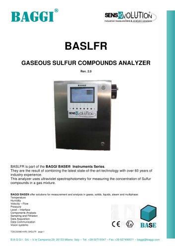
The BASE BA-RFR is part of the BAGGI BASE®
Instruments Series. They are the result of combining the
latest state-of-theart-technology with
over 50 years of
industry
experience.
The
BA-RFR
refractometer
is
designed for the
measurement
of
the refractive index (RI) of fluids (either gas or liquid) that
are transparent to the UV-Visible light. Therefore any other
physical or chemical property related to this index can be
measured. Typical applications are the measurement of the
amount of sugar in grape juice (must), or, more generally,
the concentration of solutes in a solvent.
Despite being a low-cost and a low-maintenance
-4
instrument, a resolution of 5x10 is acheived. This
refractometer is designed for in-line operation in a wide
variety of plants (from food and beverage industry to oil and
gas industry). An ATEX certified version is available for use
in potentially explosive atmospheres.
The instrument is offered either as a stand-alone system, or
integrated in a multi-purpose UV spectroscopy package,
comprising typically:
• a H2S in water analyzer (absorption measurement);
• an Oil in Water analyzer (fluorescence measurement)
• a
dissolved
Oxygen
analyzer
(fluorescence
measurement)
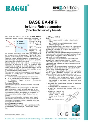
Principle of Operation
The principle of operation of the refractometer is outlined
hereafter.
The light, emitted by the spectroscope in the UV-Visible
band, is conveyed, through an optical fiber, into the cell
filled with the sample under measurement. Within the cell,
a transparent diffraction grating is placed at an angle (θin)
with respect to the direction of light. Please refer to the
drawing.
The light entering the grating is refracted by the angle θ.
The refractive index of the sample under measurement
(nsample) and the refractive index of the grating (ngrating) are
tied together by Snell’s law:
nsample⋅sin(θin) = ngrating⋅sin(θ)
θ
θ
The diffraction grating, hit by the light, originates a laterally
scattered wave with wavelength λ, according to Bragg’s
law:
TDSCS00805AR0_BARFR
λ = 2d⋅ ngrating⋅cos(θ-ϕ)
⋅
θϕ
where
• “d” is the spacing within the lattice in the diffraction
grating
• “ϕ” is the angle between the lattice plane and the
ϕ
diffraction grating surface
The diffracted wavelength λ does not exit the measurement
cell and does not reach the spectrometer, while the other
wavelengths exit the cell via an optical fiber and are
detected by the spectrometer.
An embedded computer analyses the spectrum detected by
the spectrometer, notices the missing diffracted wavelength
and calculates the refractive index of the sample by
applying Snell’s and Bragg’s laws.
The response curve (refractive index versus diffracted
wavelength) is practically linear, therefore it can be
obtained by calibrating the instrument, without the need of
knowing with high precision the physical parameters of the
diffraction grating.
A temperature sensor is available for measuring the sample
temperature, in order to compensate automatically the RI
change due to temperature variations.
The system is completed by the Control Unit, made by the
BASE® Series embedded computer and the related
actuators. This unit runs the application software for:
• collecting the measurement values from the sensors
(photometer and temperature probe); if other
instruments (such as H2S or Oil in Water analyzers)
are integrated in the system, they share the same
control unit;
• evaluating the mathematical formulas for Refractive
Index calculation;
• archiving the results in standard CSV format;
• presenting a graphical user interface (GUI) to the
Operator;
• transmitting remotely the
information/alarms
via
current
loops,
relay
signals, serial lines and
WiFi;
• calibrating the instrument;
page 1
B.A.G.G.I . SrL – V.le Campania,29 20133 Milano Italy – Tel. +39 02715547 – Fax +39 027490571 – baggi@baggi.com
"