عضویت
عضویت  ورود اعضا
 راهنمای خرید

G series0 pages

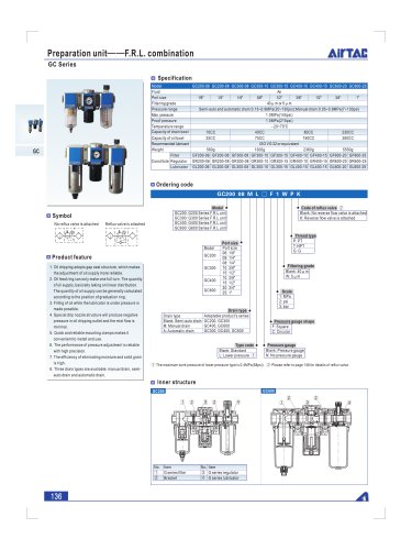
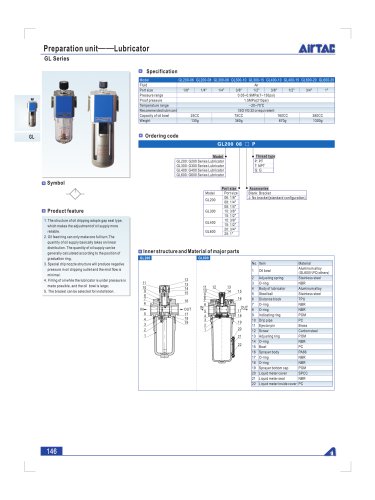
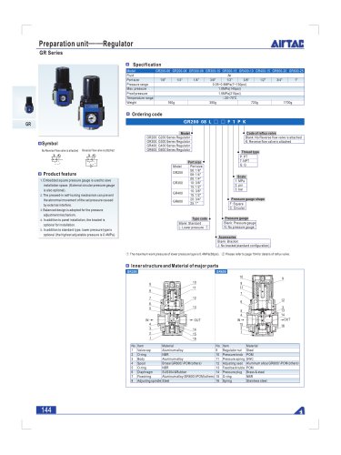
Preparation unit--Filter & regulator
AifTAC
GFR Series
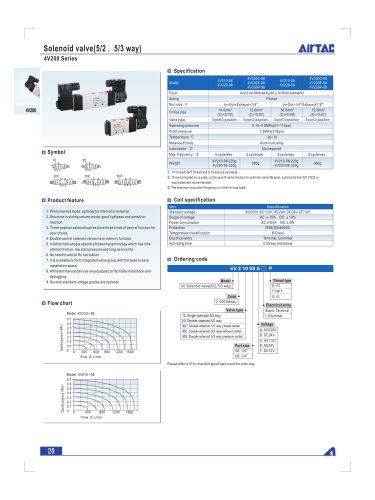
Specification
GFR200-06 GFR200-08 GFR300-08 GFR300-10 GFR300-15 GFR400-10 GFR400-15 GFR600-20 GFR600-25
Fluid | Air | |||
Port size | 1/8" | 1/4" | 1/4" | 3/8" | 1/2" | 3/8" | 1/2" | 3/4" | 1" | |||
Filtering grade | 40 u mor5 M m | |||
Pressure range | Semi-auto and automatic drain:0.15-0.9MPa(20~130psi);Manualdrain:0.05-0.9MPa(7~130psi) | |||
Max. pressure | 1.0MPa(145psi) | |||
Proof pressure | 1.5MPa(215psi) | |||
Temperature range | -20~70°C | |||
Capacity of drain bowl | 10CC | 40CC | 80CC | 230CC |
Weight | 220g | 500g | 1030g | 2400g |
□ Ordering code
GFR200 08 M L D D F 1 W P K
Model
GFR200: G200 Series filter-regulator
GFR300: G300 Series filter-regulator
GFR400: G400 Series filter-regulator
GFR600: G600 Series filter-regulator
Port size
Symbol
No reflux valve is attached Reflux valve is attached
Model | Port size |
GC200 | 06:1/8" |
08:1/4" | |
GC300 | 08:1/4" |
10:3/8" | |
15:1/2" | |
GC400 | 10:3/8" |
15:1/2" | |
GC600 | 20: 3/4" |
25:1" |
Product feature
1. Embedded square pressure gauge is used to save
installation space. (External circular pressure gauge
is also optional).
2. The pressed-in self-locking mechanism can prevent
the abnormal movement of the set pressure caused
by external interfere.
3. Balanced design is adopted for the pressure
adjustment mechanism.
4. In addition to standard type, lower pressure type is
optional (The highest adjustable pressure is 0.4MPa).
5. Unique diversion structure spins the air flowing
through to effectively sparate the liquid from the air
and reliabily filter the solid grain.
6. The filtering grade includes 5 M m and 40 u m
(optional).
7. Three drain types are available: manual drain, semi-
auto drain and automatic drain.
8. The bracket can be selected for installation.
Drain type
Drain type | Adaptable product's series |
Blank: Semi-auto drain | GFR200.GFR300 GFR400, GFR600 |
M: Manual drain | |
A: Automatic drain | GFR300, GFR400, GFR600 |
Type code
Blank: Standard
L: Lower pressure (D
Code of reflux valve
Blank: No reverse flow valve is
attached
K: Reverse flow valve is
attached
Thread type
P:PT
T: NPT
G:G
Filtering grade
Blank: 40 u. m
W:5Mm
Scale
1:MPa
2: psi
3: bar
Pressure gauge shape
F: Square
C: Circular
Pressure gauge
Blank: Pressure gauge
N: No pressure gauge
Accessories
Blank: Bracket
J: No bracket
CD The maximum work pressure of lower pressure type is 0.4MPa(58psi). ® Please refer to page 148 for details of reflux valve.
D Inner structure and material of major parts
Semi-Auto drain
Semi-Auto drain
No. | Item | Material | ||
1 | Drain bowl | Aluminum alloy(GFR600)\PC(others) | ||
2 | Umbrella baffle | High viscosity POM | ||
3 | Filter core | GFR600 | Agglomerated by brass grain | |
others | 40 M m | Agglomerated by brass grain | ||
5|jm | Makrolon fiber | |||
4 | Airguider | High viscosity POM | ||
5 | O-ring | NBR | ||
6 | Body of filter-regulator | Aluminum alloy | ||
7 | Adjusting spool | Brass (GFR600)\POM(others) | ||
8 | O-ring | NBR | ||
9 | Diaphragm | SUS304& Rubber | ||
10 | Fixation ring cap | Aluminum alloy(GFR600)\POM(others) | ||
11 | Adjusting spindle | Steel | ||
12 | Regulator nut | Steel | ||
13 | Pressure knob | POM | ||
14 | Spring | SWC | ||
15 | Adjusting seat | Aluminum alloy(GFR600)\POM(others) | ||
16 | Feedback tube | POM | ||
17 | Adjusting plug | Brass & Rubber | ||
18 | O-ring | NBR | ||
19 | Spring | SUS304 | ||
20 | Liquid meter cover | SPCC | ||
21 | Liquid meter seal | VITON | ||
22 | Liquid meter inside | PC | ||
140
"