عضویت
عضویت  ورود اعضا
 راهنمای خرید


XR-100CR Selection Chart0 pages

AMPTEK, INC. 14 DeAngelo Drive, Bedford, MA 01730-2204 U.S.A.
Tel + 1 (781) 275 2242 Fax + 1 (781) 275 3470
e-mail: sales@amptek.com www.amptek.com
XR-100 Selection Guide
In selecting a detector, the user should consider resolution, area, thickness, and peak to background.
Detector Type
Detector Area / Thickness
Guaranteed Energy Resolution eV FWHM @ 5.9 keV*
Be Window Thickness
Peak to Background Ratio**
XR-100 Part Number (must
also order PX5 to be complete system)
X-123 Part Number
(complete system)
The following detectors are fully depleted and contain a Multi-layer (ML) Internal Collimator.
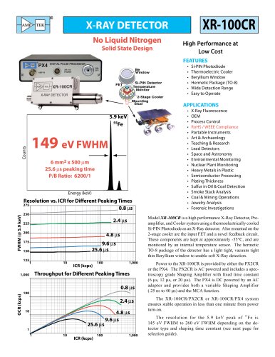
Si-PIN
6 mm2 / 500 mm
0.5 or 1.0 mil Be
145 - 165 eV
32 μs Peaking Time
P/B Ratio: 6200/1
XY-FSG32MD-G3SP (1 mil Be)
XY-FSG32MD-E2SP (0.5 mil Be)
ZY-FSG32MD-G3SP (1 mil Be)
ZY-FSG32MD-E2SP (0.5 mil Be)
Si-PIN
13 mm2 / 500 mm
1.0 mil Be
180 - 205 eV
32 μs Peaking Time
P/B Ratio: 4100/1
XY-FS432MD-G3SP
ZY-FS432MD-G3SP
Si-PIN
25 mm2 / 500 mm
1.0 mil Be
190 - 225 eV
32 μs Peaking Time
P/B Ratio: 2000/1
XY-FSJ32MD-G3SP
Super SDD
25 mm2 / 500 mm
0.5 mil Be
125 - 140 eV
11.2 μs Peaking Time
P/B Ratio: 8000/1
XY-GSJ3AMD-G2SP
ZY-FSJ32MD-G3SP
ZY-GSJ32AMD-G2SP
*Peaking Time is approximately 2.4x shaping time.
**The Peak to Background (P/B) Ratio is the ratio of the counts from 5.9 keV to 2 keV.
Amptek Detector Comparison: Resolution Range (FWHM)
25 mm² / 500 μm Si-PIN
13 mm² / 500 μm Si-PIN
6 mm² / 500 μm Si-PIN
Amptek Standard Product
25 mm² / 500 μm SDD
125
135
145
155
165
175
185
195
FWHM (eV) @ 5.9 keV
Page 1 of 2
205
215
225
235
September 2011
"