عضویت
عضویت  ورود اعضا
 راهنمای خرید


SPIRFLEX0 pages

SPIRFLEX
Application: Heating of Nozzles
SPIRFLEX
- Spiral Nozzle Heaters -
Figure 1
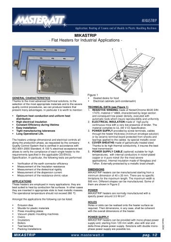
GENERAL CHARACTERISTICS
SPIRFLEX heaters represent the ideal solution when nozzles
characterised by a very small diameter need to be heated.
They are also suited in all the applications where the specific
power or the operating temperatures are very high.
These heaters, in fact, can be provide a heating power as
2
high as 8 W/cm and can reach operating temperatures up to
600 °C. They can heat nozzles starting from a minimum
diameter of 6 mm (8 mm with 24 and 25 series).
These heaters need a minimum clearance to be installed: the
difference between the heater external diameter (D) and the
spiral internal diameter (Di) is always in the range 6 to 8 mm.
APPLICATIONS
These heaters are employed in all the plastic moulding
machines where the operational temperature does not
exceed 600 °C. They are particularly useful whenever a
limited clearance is available between nozzle and mould (e.g.
in hot-chamber moulds).
SPIRFLEX
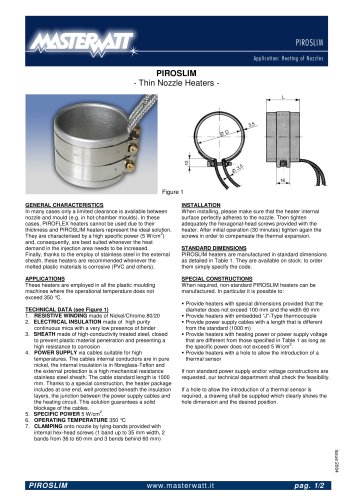
ROLLING
To roll SPIRFLEX heaters please
use a chuck and operate as
shown in the sketch aside. Chuck
diameter G shall be < Φ nozzle to
compensate the residual elasticity
of the heater after rolling.
STANDARD DIMENSIONS
SPIRFLEX heaters are manufactured in standard dimensions
as detailed in the tables below. They are available on stock:
to order them simply specify the code.
SPECIAL CONSTRUCTIONS
When required, non-standard SPIRFLEX heaters can be
manufactured. In particular it is possible to:
§Manufacture heaters with a length up to 3000 mm (series
24 and 25) or 1200 mm (other series)
§Provide power supply cables with a length that is different
from the standard (1000 m) or oriented differently from the
standard (see figure below for the alternatives)
180° Orientation
90° Orientation
§Provide heaters with heating power or power supply voltage
that are different from those specified in tables below as
long as the following conditions are respected:
o Supply Voltage in the range 24 ÷ 250 V
o Current below 5A (series 24 and 25) or 4A (other series)
o Maximum Power:60 W/100 mm
o Minimum power at 220 V: 180 W/300 mm
If non standard power supply and/or voltage constructions are
requested, our technical department shall check the feasibility.
www.masterwatt.it
pag. 1/2
Issue 2004
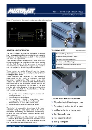
TECHNICAL DATA
1. RESISTIVE WINDING made of Nickel/Chrome 80/20
2. ELECTRICAL INSULATION made of compressed
mineral oxide
3. EXTERNAL SHEATH made of INCOLOY 800
4. TERMINAL EDGE welded, water-tight, with about 6 mm
neutral section
5. POWER SUPPLY via bipolar cables suitable for high
temperatures. The cables internal conductors are in pure
nickel, the internal insulation is in fibreglass-Teflon and
the external protection is a stainless steel sheath. The
cable section is 0.75 mm², its standard length is 1000 mm
and the standard inclination (see Figure 1) is 45°. The
cables are blocked by means of a bush that is seamed
onto the heater sheath thus providing adequate sealing in
case some plastic material leaks from the nozzle. The
neutral section is made by a couple of nickel-chrome
wires that are welded to the power supply cables
2
6. SPECIFIC POWER up to 8 W/cm .
7. OPERATING TEMPERATURE up to 600 °C
8. THERMOCOUPLE (optional) J-type, embedded in the
heater, placed 5 mm before the terminal edge and
electrically connected by two compensated cables, PTFE
insulated, characterised by a section of 0.5 mm²
9. DIELECTRIC RIGIDITY capable to insure a dispersion
current below 0.5 mA when 1250V are applied between
the heating circuit and the sheath (results relevant to
straight element). The same value is guaranteed between
heating circuit and thermocouple with test voltage 600V.
INSTALLATION
When installing, please make sure that the heater internal
surface perfectly adheres to the nozzle.