عضویت
عضویت  ورود اعضا
 راهنمای خرید


IRC-AT Carbon Dioxide0 pages

IRC-AT CARBON DIOXIDE
IRC-A
C-AT
DIOXIDE
INFRARED SENSOR
Thermopile Detector
Technical Specification
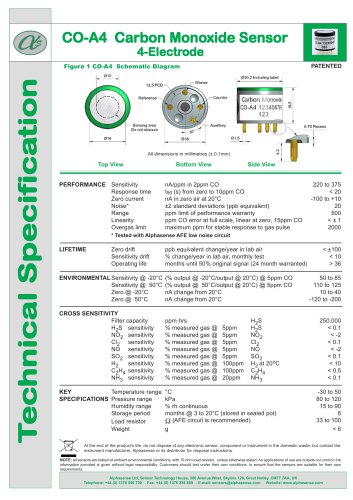
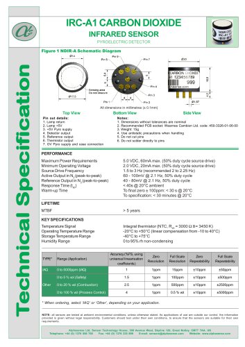
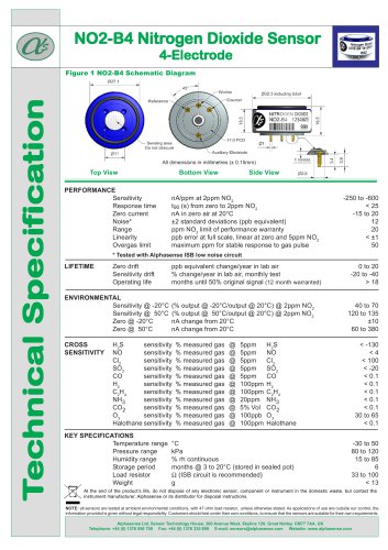
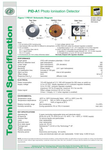
Figure 1 IRC-AT Schematic Diagram
All dimensions in millimetres (± 0.15mm)
Top View
Pin out details:
1. Lamp return
2. Lamp +5V
3. Not connected
4. Detector output.
5. Reference output
6. Thermistor output
7. OV supply
Bottom View
Side View
Notes:
1. Dimensions without tolerances are nominal
2. Recommended PCB socket: Wearnes Cambion Ltd. code: 450-3326-01-06-00
3. Weight: 15g
4. Use antistatic precautions when handling
5. Do not cut pins
6. Do not solder directly to pins
PERFORMANCE
Maximum Power Requirements
Minimum Operating Voltage
Source Drive Frequency
Active Output in N2 (peak-to-peak)
Reference Output in N2 (peak-to-peak)
Response Time (t90)
Warm-up Time
5.0 VDC, 60 mA max. (50% duty cycle source drive)
2.0 VDC, 20 mA max. (50% duty cycle source drive)
3 Hz
4 to 7 mV @ 3 Hz, 50% duty cycle
2 to 5 mV @ 3 Hz, 50% duty cycle
< 40 s @ 20°C ambient
To final zero ± 100 ppm: < 30 s @ 20°C
To specification: < 30 minutes @ 20°C
LIFETIME
MTBF
> 5 years
KEY SPECIFICATIONS
Temperature Signal
Operating Temperature Range
Storage Temperature Range
Humidity Range
Integral thermistor (NTC, R25 = 100KΩ B= 3940 K)
-20°C to +50°C (linear compensation from 0 to 40°C)
-40°C to +75°C
0 to 95% rh non-condensing
TYPE*
Range (Application)
Accuracy (%FS, using
universal linearisation
coefficients)
Zero
Resolution
(ppm)
Full Scale
Resolution
(ppm)
Zero
Repeatability
(ppm)
Full Scale
Repeatability
(ppm)
IAQ
0 to 5000ppm (IAQ)
1
10
50
± 20
± 50
0.000325
0.9363
4000 ppm
0 to 5 % vol (Safety)
1.5
10
100
± 20
± 500
0.5411
0.6716
4%
0 to 20 % vol (Combustion)
2.5
10
2000
± 20
± 2500
1.0459
0.2932
16%
0 to 100 % vol (Process Control)
tbc
10
tbc
± 20
tbc
tbc
tbc
100%
Other
Span
Universal Universal
calibration
lin. coeff. b lin. coeff. c
conc.
At the end of the product’s life, do not dispose of any electronic sensor, component or instrument in the domestic waste, but contact the
instrument manufacturer, Alphasense or its distributor for disposal instructions.
NOTE: all sensors are tested at ambient environmental conditions, with 47 ohm load resistor, unless otherwise stated. As applications of use are outside our control, the
information provided is given without legal responsibility. Customers should test under their own conditions, to ensure that the sensors are suitable for their own requirements.
Alphasense Ltd, Sensor Technology House, 300 Avenue West, Skyline 120, Great Notley. CM77 7AA. UK
Telephone: +44 (0) 1376 556 700 Fax: +44 (0) 1376 335 899 E-mail: sensors@alphasense.com Website: www.alphasense.com